Productivity Lift.pdf - 第73页
User Manual - Productivity Lift Soko 00166631-01 / 12031477 6 Set-up mode Software version V 43.140 Edition April 2006 65 6 Set-up mode In set-up mode, it is po ss ible to enter and modify parameters that do not serve th…
5 Configuration User Manual - Productivity Lift Soko 00166631-01 / 12031477
5.27 Input identity number Software version V 43.140 Edition April 2006
64
User Manual - Productivity Lift Soko 00166631-01 / 12031477 6 Set-up mode
Software version V 43.140 Edition April 2006
65
6 Set-up mode
In set-up mode, it is possible to enter and modify parameters that do not serve the basic setting
of the system, but that, for example, show the values dependent on the size of the machine type.
Press the „ALT” key to access the „set-up mode” menu.
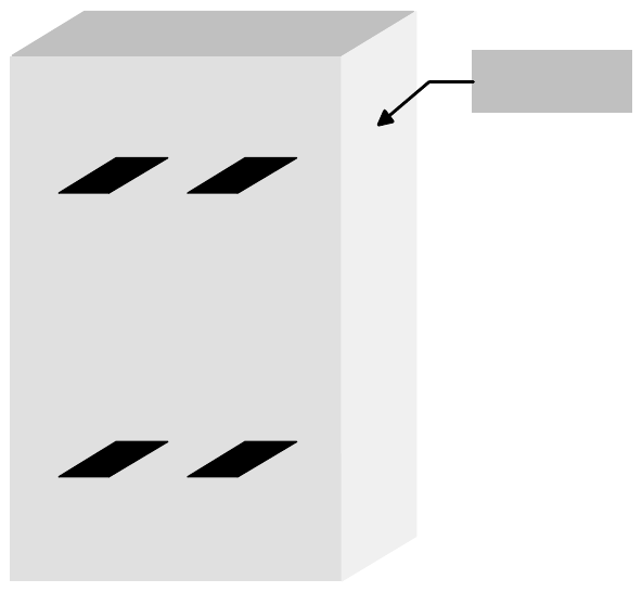
Definition:
View of the direction of transit.
Fig. 6 - 1 Definition / Schematic of the transport tracks
Spur 2
Track 2
Spur 1
Track 1
Spur 4
Track 4
Spur 3
Track 3
Bedienseite
Operating side
6 Set-up mode User Manual - Productivity Lift Soko 00166631-01 / 12031477
6.1 Identity number Software version V 43.140 Edition April 2006
66
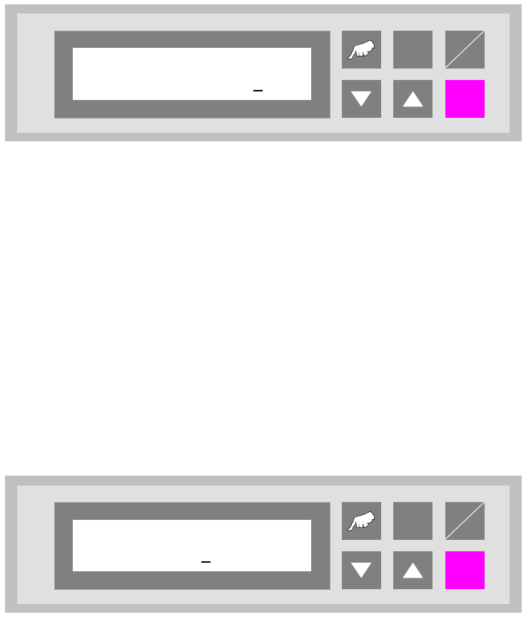
6.1 Identity number
This selection can be used to assign an identification number to the following set of parameters.
When starting the system, only the corresponding PCB number need be called up, and the system
sets the stored parameters automatically. The number consists of two assignment digits and one
eight-digit identification. The assignment digits can be used to call up the parameter set when
starting the system. The eight-digit identification can be changed at random and only serves the
input of user-specific identification numbers. Each number has only one numerical entry.
Fig. 6 - 2 Identity number
6.2 Width board
This menu item is only active if the settings „automatic” or „only at start” were selected in the chap-
ter „Width adjusting”.
The value to be entered here can be used to prescribe the transport width of the system numeri-
cally as an absolute value. After starting the automatic operating mode, and after each width ad-
justment reference run, the width prescribed here is automatically reset.
The unit of value is [0.1 mm] in a setting range of 500 to maximum width (corresponds to 50 mm
to maximum width).
Fig. 6 - 3 Width board
ALT
Enter
Start
Stop
Ident number
01 00000001
ALT
Enter
Start
Stop
Width board
4600