Productivity Lift.pdf - 第92页
7 Manual mode User Manual - Producti vity Lift Soko 00166631-01 / 12031477 7.5 Manual mode 6 - Width belts Software version V 43.140 Edition April 2006 84
User Manual - Productivity Lift Soko 00166631-01 / 12031477 7 Manual mode
Software version V 43.140 Edition April 2006 7.4 Manual mode 5 - Width Lift
83
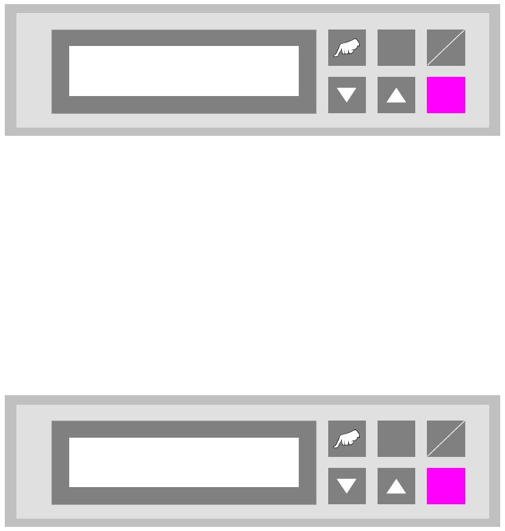
7.4 Manual mode 5 - Width Lift
Function to set the width for the shuttle conveyors.
The cursor keys "V" and "W" can be used to increase and/or decrease the width of the conveyors.
The "Enter" key can be used to proceed to the next test function. To cancel the procedure, exit
the menu using the "Start/Stop" key.
Fig. 7 - 4 Manual mode 5 - Width Lift
7.5 Manual mode 6 - Width belts
Function to set the width for the underfloor conveyor.
The cursor keys "V" and "W" can be used to increase and/or decrease the width of the conveyor.
The "Enter" key can be used to return to the first test function. To cancel the procedure, exit the
menu using the "Start/Stop" key.
Fig. 7 - 5 Manual mode 6 - Width belts
ALT
Enter
Start
Stop
Manual mode 5
Width Lift
ALT
Enter
Start
Stop
Manual mode 6
Width belts
7 Manual mode User Manual - Productivity Lift Soko 00166631-01 / 12031477
7.5 Manual mode 6 - Width belts Software version V 43.140 Edition April 2006
84
User Manual - Productivity Lift 8 Automatic tracking
Edition 02/2004 8.1 Automatic tracking via hybrid light barriers
85
8 Automatic tracking
The Productivity Lift can be fitted with two types of automatic tracking.
1. Tracking via hybrid light barriers
2. Tracking via CAN bus
8.1 Automatic tracking via hybrid light barriers
The system is equipped with an automatic tracking facility for the transport width.
In the automatic operating mode, the transport width is tracked automatically. Built-in hybrid light
barriers detect the position of the mobile transport cheek of the previous or following device and
automatically adapt the transport width of the lift. The sensor mechanism detects the direction in
which adjustment is made and proceeds accordingly. If signals overlap, a reference run is per-
formed. In this case, the width setting is increased to the maximum width and then the transport
width is reset.
8.2 Automatic tracking via CAN-Bus
The lift is connected to other systems via a CAN bus. The data for the current width are transferred
via this CAN bus. The configuration of the lift determines which system is responsible for the width
and how the width is queried and checked.
Communication via CAN bus is only possible with our systems.