00196044-05 - sg x und x4i fse_en.pdf - 第107页
Communication and Control CAN Bus Structure CAN Bus S tudent Guide (FSE) SIPL ACE X Series and X4I Edition 01/2009 EN Communication and Control 107 4.3.3.3 CAN Bus Concept SiplaceX4 4-18: CAN Bus overview SIPLACE X4 SMP …
Communication and Control
CAN Bus CAN Bus Structure
Student Guide (FSE) SIPLACE X Series and X4I
Communication and Control Edition 01/2009 EN
106
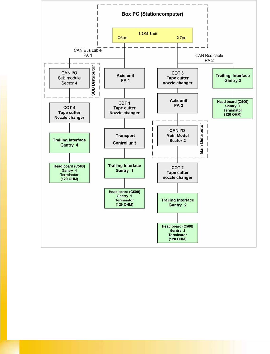
4.3.3.2 CAN Bus Concept SiplaceX3
4-17: CAN Bus overview SIPLACE X3
The placement machine SIPLACE X3 uses a bus system with 1 Mbit/s transmission rate. The bus
system begins at the communication board and is split in 2 paths. Every path is terminated by a 120 ohm
terminator on the head board at the individual placement head.
NOTE:
When the Twin head is mounted, the switch for the terminator on the head board (C500) must
be OFF.
Communication and Control
CAN Bus Structure CAN Bus
Student Guide (FSE) SIPLACE X Series and X4I
Edition 01/2009 EN Communication and Control
107
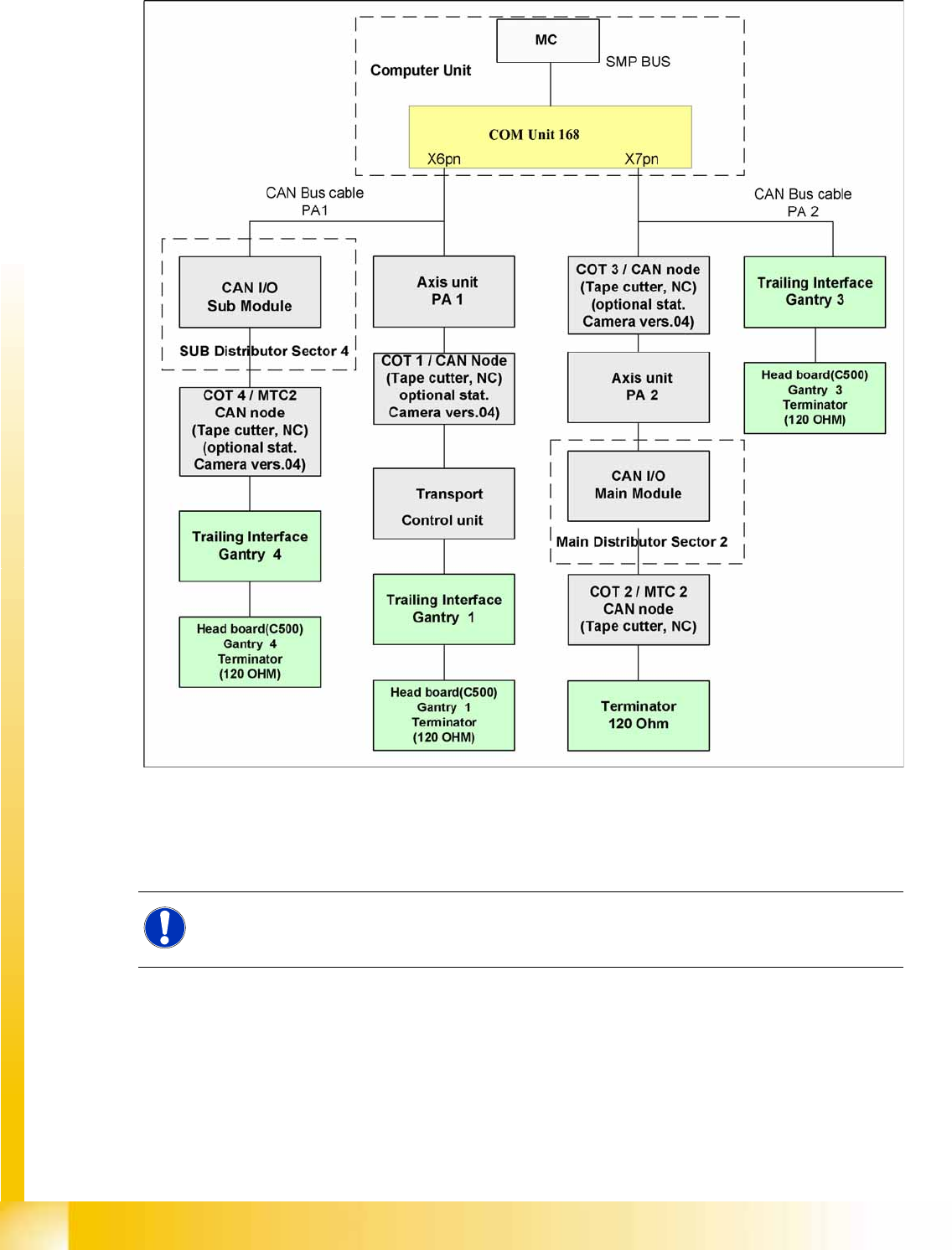
4.3.3.3 CAN Bus Concept SiplaceX4
4-18: CAN Bus overview SIPLACE X4
SMP = Small Micro Prozessor
The placement machine SIPLACE X4 uses a bus system with 1 Mbit/s transmission rate.The CAN: The
bus system begins at the communication board and is split in 2 paths. Every path is terminated by a 120
ohm terminator on the head board at the individual placement head.
Communication and Control
CAN Bus CAN Bus Structure
Student Guide (FSE) SIPLACE X Series and X4I
Communication and Control Edition 01/2009 EN
108
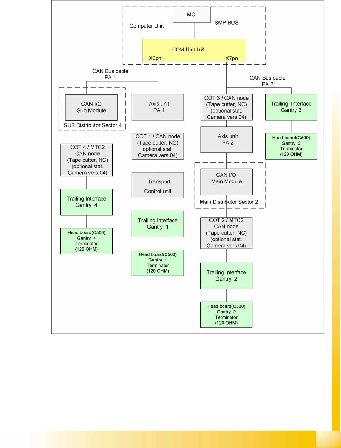
4.3.3.4 CAN Bus Concept Siplace X4I
4-19: CAN Bus overview SIPLACE X4I
The placement machine SIPLACE X4I uses a bus system with 1 Mbit/s transmission rate. The bus
system begins at the communication board and is split in 2 paths. Every path is terminated by a 120 ohm
terminator on the head board at the individual placement head.