00196044-05 - sg x und x4i fse_en.pdf - 第119页
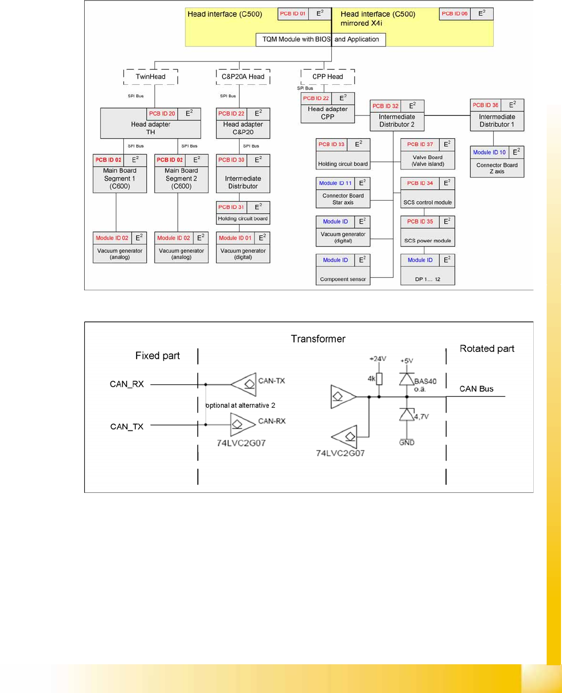
Communication and Control Communication CPP Head CAN Bus S tudent Guide (FSE) SIPL ACE X Series and X4I Edition 01/2009 EN Communication and Control 11 9 4.3.8.3 EEPROMs on CPP Head EEPROMs are pr esent on all boa rds (e…
Communication and Control
CAN Bus Communication CPP Head
Student Guide (FSE) SIPLACE X Series and X4I
Communication and Control Edition 01/2009 EN
118
4.3.8 Communication CPP Head
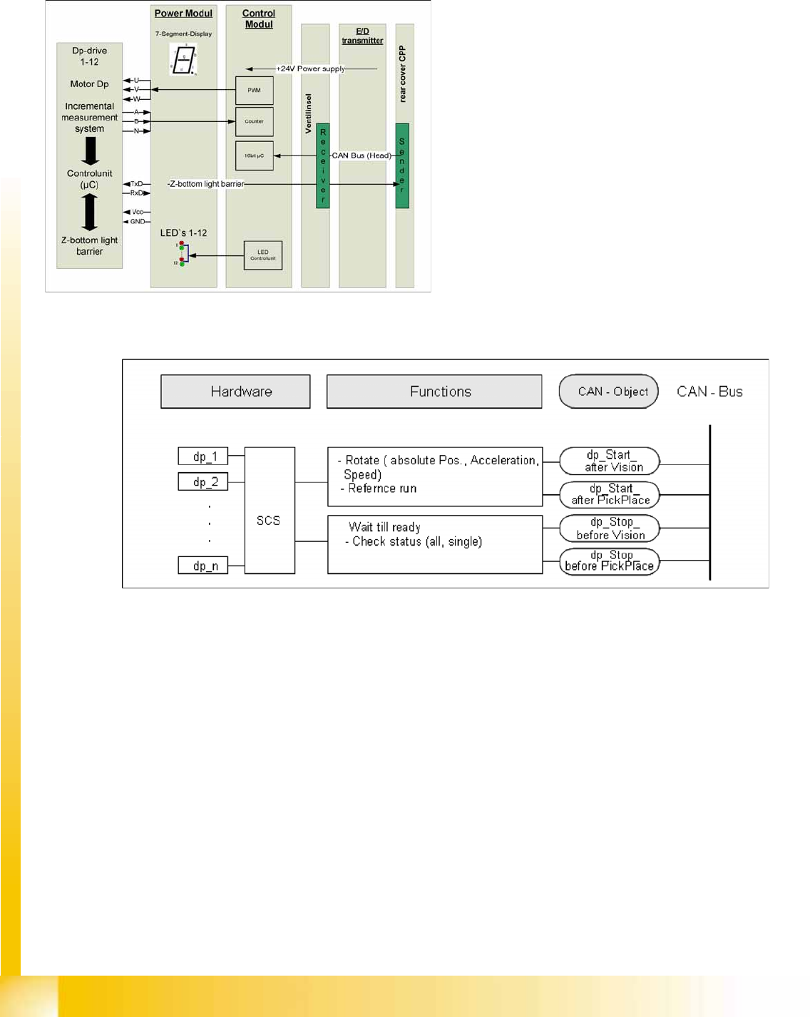
4.3.8.1 Communication to the DP Drives
4.3.8.2 CAN Bus Communication to the DP Drives
The data is supplied via the head CAN bus, from the head interface to the intermediate distributor.
The four CAN bus commands are identical to those for the C&P20A head:
Starts a certain rotary axis after pickup/placement.
Starts a certain rotary axis after Vision.
Waits for a certain rotary axis before Vision.
Waits for a certain rotary axis before pickup/placement.
The DP drives are controlled via a common
hardware component, the SCS (Single Core
Solution). This consists of two boards, the power
and the control modules, with a microprocessor for
the sequence control.
The control data is sent from the head processor
and is then transmitted via the head CAN bus.
The communication with the light barrier Z down is
via a separate interface, directly to the power
module. This is necessary as a light barrier Z down
is integrated into each segment.
Communication and Control
Communication CPP Head CAN Bus
Student Guide (FSE) SIPLACE X Series and X4I
Edition 01/2009 EN Communication and Control
119
4.3.8.3 EEPROMs on CPP Head
EEPROMs are present on all boards (except E/D transformer). Various data are stored there, according
to the individual functions e.g. production date, material number, zero point correction values, offset
values, plus operating and statistical data.
4.3.8.4 Data Transfer
The communication with the DP drives (CAN bus) is contactless via a transmitter unit (on the back
cover of the CPP head) and a receiver unit (on the valve terminal).
This communication is via 2 channels, whereby channel 1 is responsible for supplying data to the
DP drives and channel 2 is responsible for communication to the Z down light barrier of the axis card
(HCU).
The head CAN bus is – in this case – not used as a differential CAN bus with the CAN_L and CAN_H
signals but as a 1 wire CAN on the rotor.
Communication and Control
CAN Bus X Feeder - Communication
Student Guide (FSE) SIPLACE X Series and X4I
Communication and Control Edition 01/2009 EN
120
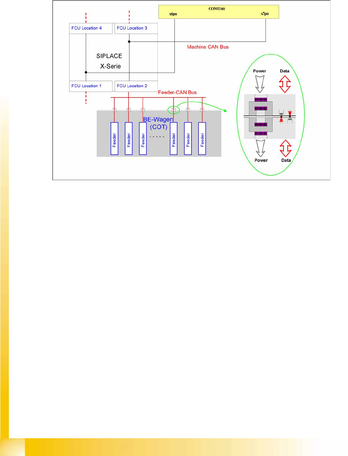
4.3.9 X Feeder - Communication
4-28: Communication X feeder
The communication between the Feeder Control Unit (FCU) and each X feeder is carried out via a CAN
bus. This CAN bus is only responsible for the communication between the FCU and the feeders and is
controlled by the machine CAN bus.
The data and power supply from the FCU to each feeder is contactless.