00196044-05 - sg x und x4i fse_en.pdf - 第126页
Communication and Control CAN Bus CAN I/O Module (SLIO) SIPLACE X S tudent Guide (FSE) SI PL ACE X Series and X4I Communication and Control Edition 01/2009 EN 126 4.3.10.5 I/O Module, Subdistributor (Output s) nc= not co…
Communication and Control
CAN I/O Module (SLIO) SIPLACE X CAN Bus
Student Guide (FSE) SIPLACE X Series and X4I
Edition 01/2009 EN Communication and Control
125
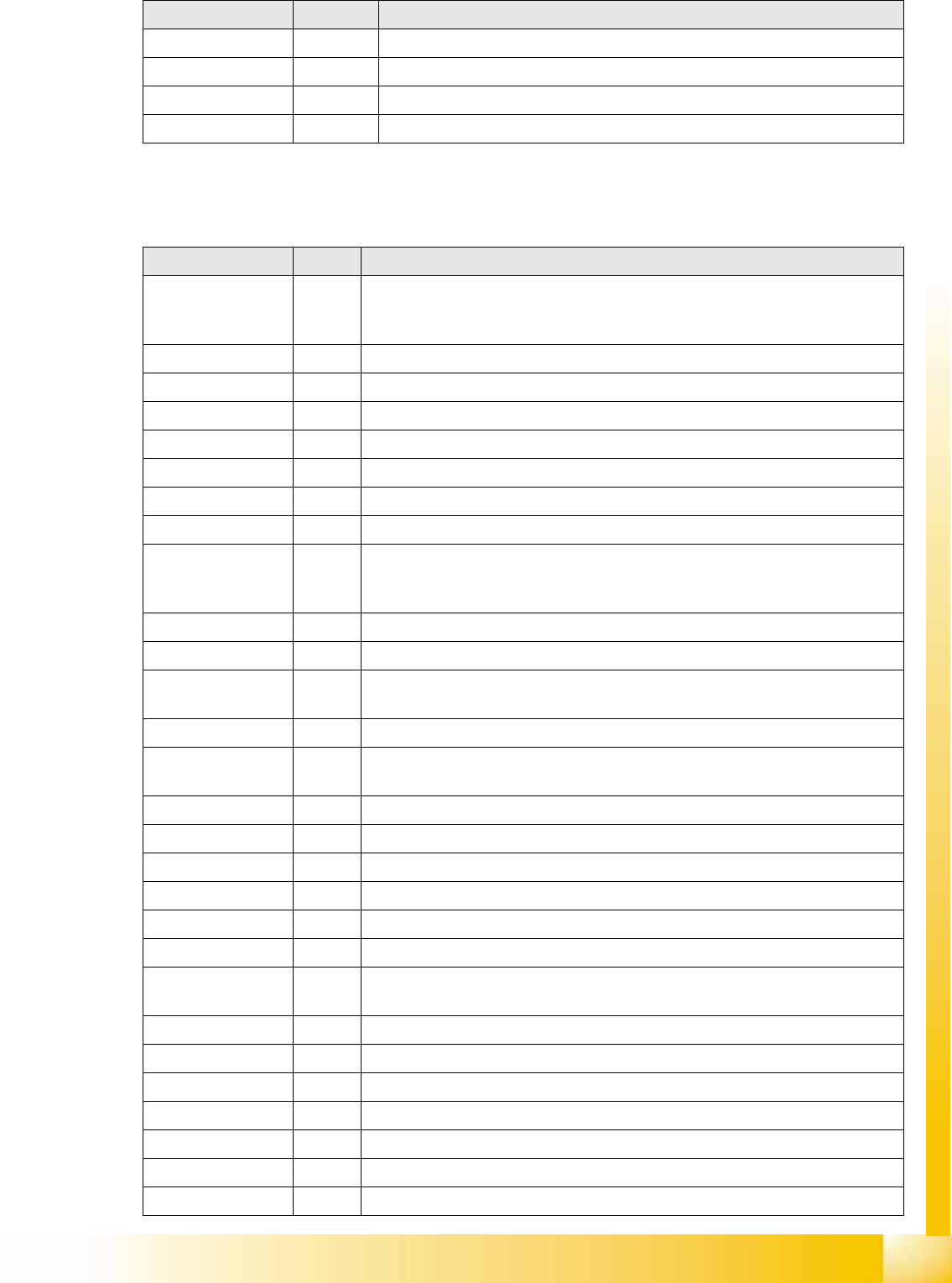
4.3.10.4 I/O Module, Subdistributor (Inputs) [new: 03046226-01]
nc= not connected (Reserve)
X9_5 GND
X9_6 GND
X9_7 GND
X9_8 GND
Terminals I / O Description / Note
Terminals I / O Description / Note
X3_1 Di0 M_NotAusSchleife1ok or M_Security Loop ("high" if all safety loops are closed
(protective hoods, emergency STOP buttons, component flaps, changeover
tables).
X3_2 Di1 nc
X3_3 Di2 nc
X3_4 Di3 nc
X3_5 Di4 nc
X3_6 Di5 M_Drucksensor Hauptventil/ "high" signal when compressed air level is reached
X3_7 Di6 M_Vakuumpumpe EIN
X3_8 Di7 nc
X4_1 Di8 M_StartTaste "high" signal while the start button is pressed. The function of this
button triggers the protective contactor combination, all axes are ready for
operation.
X4_2 Di9 M_StopTaste"high" signal while the stop button is pressed. .
X4_3 Di10 nc
X4_4 Di11 M_ PortalCrash2 "low" signal gantries 1 and 4 too close,"high" signal is normal
operating status
X4_5 Di12 nc
X4_6 Di13 M_ ServoEnable2 or Steuerung Ein/"high" signal intermediate circuit voltage for
X/Y servo on axis unit 2 - switched through. (K4 message)
X4_7 Di14 nc
X4_8 Di15 M_ NotAusTasteMTC/"high" signal - emergency STOP button activated.
X5_1 Di16 nc
X5_2 Di17 M_ Haube1 "high" signal if cover 1 is closed.
X5_3 Di18 M_ BE-Tisch1 "high" signal if changeover table 1 is docked.
X5_4 Di19 M_ HaubeLP-Eingabe "high" signal if the cover above the PCB input is closed.
X5_5 Di20 M_ NotAusTasteLP-Eingabe "high" signal if the emergency STOP button is
unlocked.
X5_6 Di21 M_ Haube4 "high" signal if cover 4 is closed.
X5_7 Di22 M_BE-Tisch4 "high" signal if changeover table 4 is docked.
X5_8 Di23 nc
X5_8 Di23 nc
X6_1 nc
X6_2 nc
X6_3 GND
Communication and Control
CAN Bus CAN I/O Module (SLIO) SIPLACE X
Student Guide (FSE) SIPLACE X Series and X4I
Communication and Control Edition 01/2009 EN
126
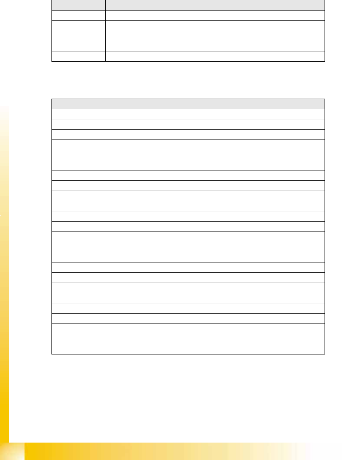
4.3.10.5 I/O Module, Subdistributor (Outputs)
nc= not connected (Reserve)
X6_4 nc
X6_5 nc
X6_6 nc
X6_7 nc
X6_8 nc
Terminals I / O Description / Note
Terminals I / O Description / Note
X7_1 Do0 nc
X7_2 Do1 nc
X7_3 Do2 nc
X7_4 Do3 nc
X7_5 Do4 nc
X7_6 Do5 St_Vakuumpumpe EIN
X7_7 Do6 nc
X7_8 Do7 nc
X8_1 Do8 nc
X8_2 Do9 nc
X8_3 Do10 nc
X8_4 Do11 nc
X8_5 Do12
X8_6 Do13
X8_7 Do14
X8_8 Do15
X9_1 24 V
X9_2 24 V
X9_3 24 V
X9_4 24 V
X9_5 GND
X9_6 GND
X9_7 GND
X9_8 GND
Communication and Control
Tape Cutter and Nozzle Changer - Communication CAN Bus
Student Guide (FSE) SIPLACE X Series and X4I
Edition 01/2009 EN Communication and Control
127
4.3.11 Tape Cutter and Nozzle Changer - Communication
Description of CAN node NC tape cutter module
The introduction of the SIPLACE X4I and the further development of the SIPLACE X series also brings
with it the integration of the nozzle changer control and the monitoring sensors into the machine CAN
bus.
This new board is named "CAN node NC tape cutter module" [03052927-xx] and is used in place of the
former tape cutter board.
This board contains the control system for the tape cutter unit, NC 1 and 2, nozzle station (blast air valve
for C&P20A head) and sensors for the component/nozzles reject bin.
The firmware for the CAN nodes is loaded onto the tape cutter board with the help of the station software
or CACCIA.
The "CAN node NC tape cutter" is backwards compatible with the old tape cutter boards. This assembly
can therefore be used in X, HF and D series machines.
Based on the cables connected and the position of the DIP switch, the CAN processor detects which
functions are to be controlled and at which location each assembly is.
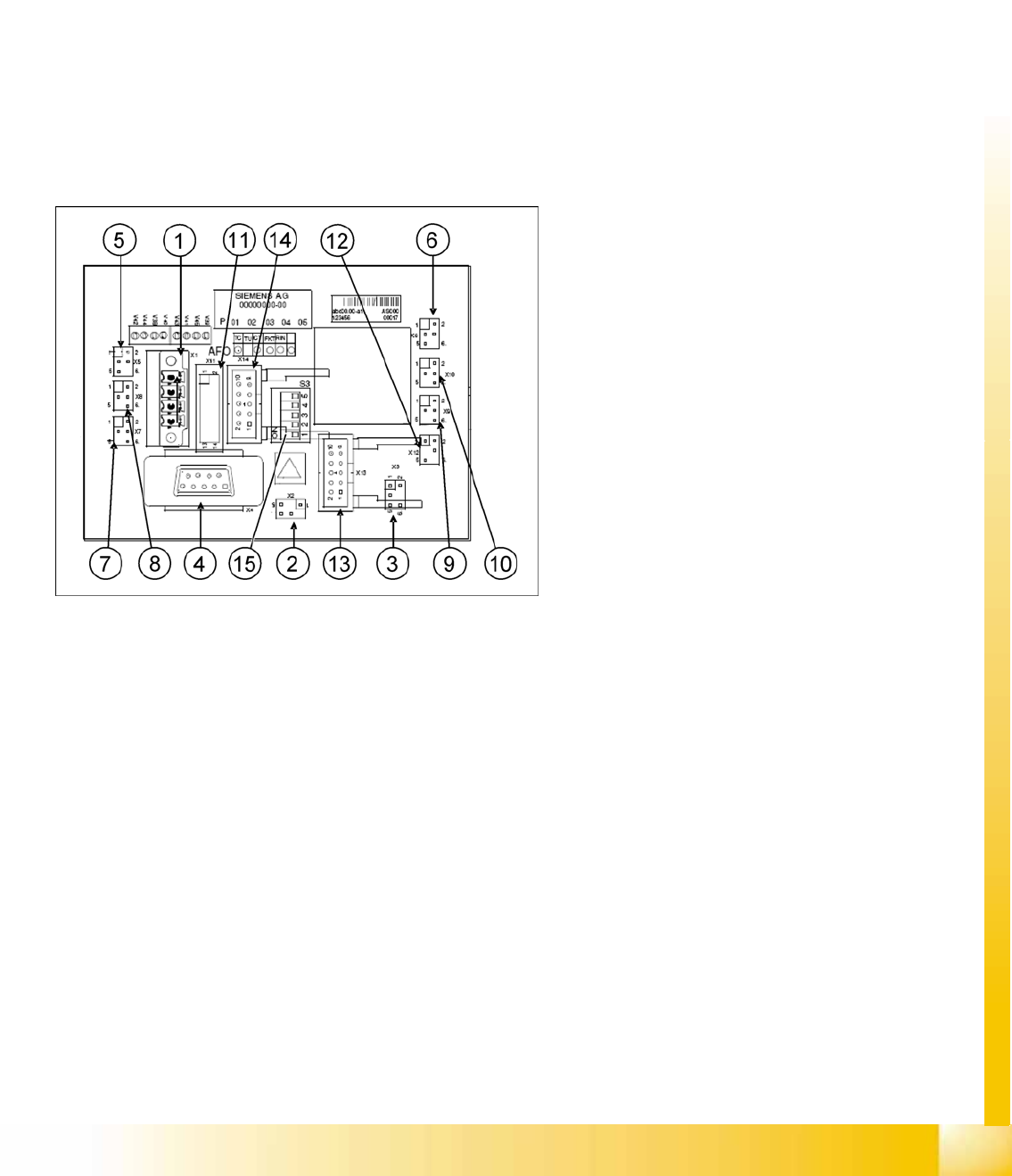
CAN node NC tape cutter module
1. X1 – Energy supply with automatic CAN ID
2. X2 – Energy supply, tape cutter +24 V/+5 V
3. X3 – Reject bin (nozzles, components)
4. X4 – CAN bus connection
5. X5 – Energy supply to valve (left)
6. X6 – Energy supply to valve (right)
7. X7 – Proximity switch for stroke cylinder in
(left)
8. X8 – Proximity switch for stroke cylinder out
(left)
9. X9 – Proximity switch for stroke cylinder in
(right)
10. X10 – Proximity switch for stroke cylinder out
(right)
11. X11– Test connector, tape cutter
12. X12 – Compressed air valve (additional
pneumatic unit for rejecting components)
13. X13 – Nozzle changer, row 1
14. X14 – Nozzle changer, row 2
15. DIP switch group S3