00196044-05 - sg x und x4i fse_en.pdf - 第130页
Communication and Control Axis Control Position Measuring System S tudent Guide (FSE) SI PL ACE X Series and X4I Communication and Control Edition 01/2009 EN 130 4-31: Principle signal multiplication at analog Track sign…
Communication and Control
Position Measuring System Axis Control
Student Guide (FSE) SIPLACE X Series and X4I
Edition 01/2009 EN Communication and Control
129
4.4 Axis Control
4.4.1 Position Measuring System
4.4.1.1 Track Signals and Axis Zero Pulse Signal
Our Axes systems consists of the following parts.
Axis controller for main board
Servo amplifier
Motor
Position measuring system with Incremental- scale and -encoder
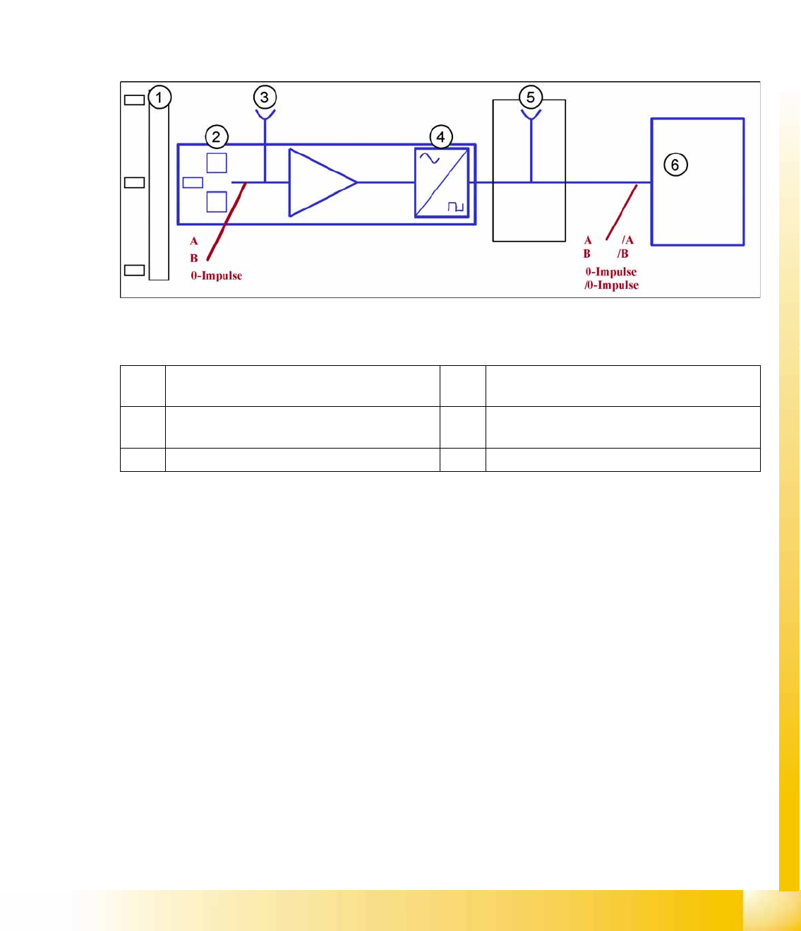
4-30: Principle circuit for position measuring systems
Legend
The axis control system with closed position control circuit determines the axis position directly,
based on the mechanical movement of the axis. The position measurement system generates analog
track and zero pulse signals during movement over the incremental scale. An amplifier, a frequency
multiplier circuit and a signal former are integrated into the amplifier housing. A test connector for digital
signals is either installed on the next interface board or the digital signals are measured at track A/B and
the zero pulse output of the SIPLACE AxisTester. The track signals are the only feedback loops in all
the axis control systems of the SIPLACE machine. This means that each track recognition error affects
the axis control system. The gantry axes immediately stop at a fault; the head axes finish the positioning
to target before showing a track signal error.
The position is determined by a position counter on the axis controller. The direction of axis movement
is determined by the phase shift of the two track signals An advanced track A signal indicates movement
to the right, while an advanced track B signal indicates movement to the left. To make the encoder
system robust for the high resolution we multiply the frequency of the analog signal and create a high
resolution digital measuring system.
1 Incremental scale with zero pulses 4 Electronic signal multiplication and signal
digitalization
2 Incremental encoder for track A / B and
Zeropulse signals (O-pulse.)
5 Test output digital signals
3 Analog signal output and amplifier 6 Axis controller
Communication and Control
Axis Control Position Measuring System
Student Guide (FSE) SIPLACE X Series and X4I
Communication and Control Edition 01/2009 EN
130
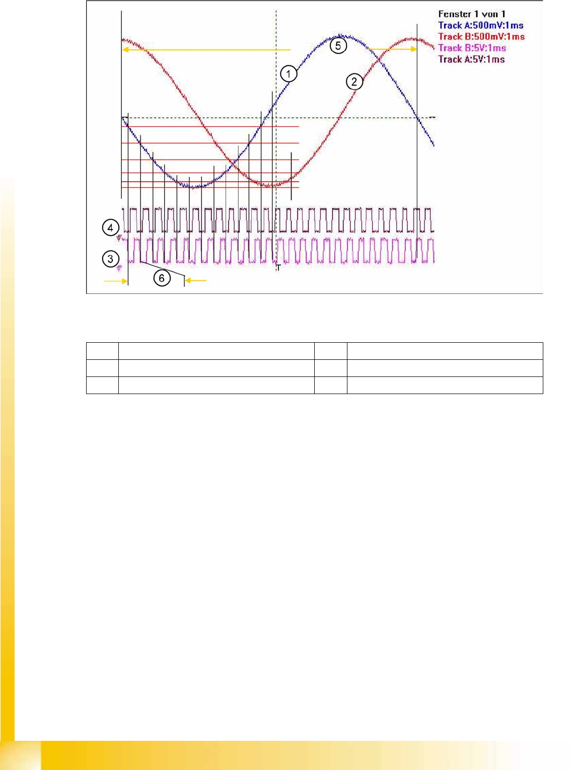
4-31: Principle signal multiplication at analog Track signals of a gantry axis
Legend
The signal multiplication can be realized as a Schmitt trigger action. During comparison of the analog
and digital axis signals, a signal multiplication of 25 (see diagram above), 10 or just 1 can be recognized.
The track signals for the C&P axes can only be measured as digital signals. The analog signals are
directly converted in the transmitter housing, without provision of a test connection for the analog signals.
1 Analog track A signal incremental encoder 4 Digital track B signal at Test connector
2 Analog track B signal incremental encoder 5 Analog track signal period
3 Digital track A signal at Test connector 6 Period time of digital track signal
Communication and Control
Position Measuring System Axis Control
Student Guide (FSE) SIPLACE X Series and X4I
Edition 01/2009 EN Communication and Control
131
4.4.1.2 Zero Pulse at the Track Signal Encoder
Each incremental encoder system needs initializing. This means a reference run is performed for each
axis. During the reference run, each axis searches for a certain point, the zero pulse. The zero pulse is
an analog signal which is digitized by a ’Schmitt Trigger’ circuit.
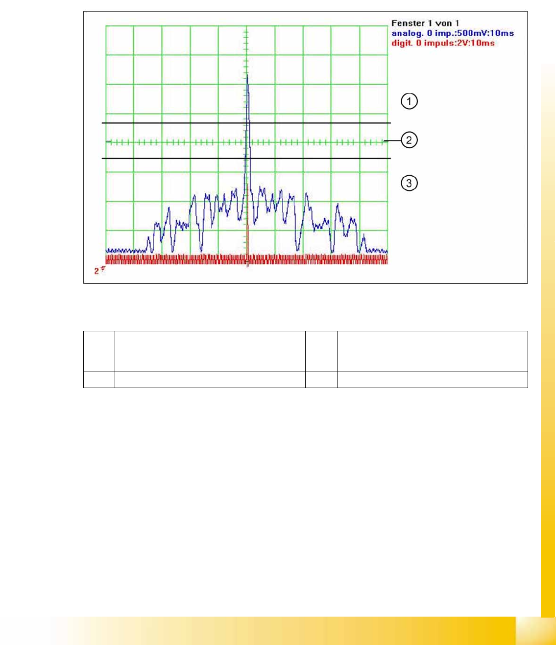
When this fiducial is passed over (zero pulse) on the incremental measuring system, a zero pulse signal
is issued. This is an analog signal (1).
(Measurement of analog signal by setting the
zero line
at the center of the screen)
4-32: Analog and digital zero pulse signal (zero line set at screen center)
Legend
At around 2.5 V the Schmitt trigger circuit issues a brief, high pulse: the zero pulse for the position
measurement system. If the encoder has been installed too near to the incremental scale, one of the
auxiliary pulses could exceed the Schmitt trigger threshold and be mistakenly recognized as the zero
pulse. In older SIPLACE machines, this leads to a placement offset.
The further development of the encoder (one field scan) and improved software have fixed most of these
errors. This means that the search for the zero pulse is only performed over a defined area of the
incremental measuring system (50 mm). If the pulse is found in this area, further pulses will be searched
for in an area of approx. +/- 2.5 mm. If two or more pulses are detected, an error message will be issued.
This ensures that only one zero pulse exists in this area.
1 The analog zero pulse needs to be 0.3 V higher
than the trigger threshold for the digital zero
pulse.
3 Glitches (signal noise) should not override the
limit 0,3 V less than Trigger threshold!
2 Schmitt Trigger Threshold