00196044-05 - sg x und x4i fse_en.pdf - 第132页
Communication and Control Axis Control Axis Dynamic Basics S tudent Guide (FSE) SI PL ACE X Series and X4I Communication and Control Edition 01/2009 EN 132 4.4.2 Axis Dynamic Basics Each axis starts from a position with …
Communication and Control
Position Measuring System Axis Control
Student Guide (FSE) SIPLACE X Series and X4I
Edition 01/2009 EN Communication and Control
131
4.4.1.2 Zero Pulse at the Track Signal Encoder
Each incremental encoder system needs initializing. This means a reference run is performed for each
axis. During the reference run, each axis searches for a certain point, the zero pulse. The zero pulse is
an analog signal which is digitized by a ’Schmitt Trigger’ circuit.
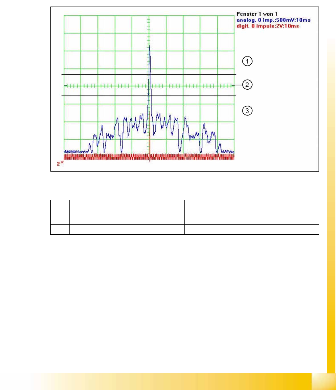
When this fiducial is passed over (zero pulse) on the incremental measuring system, a zero pulse signal
is issued. This is an analog signal (1).
(Measurement of analog signal by setting the
zero line
at the center of the screen)
4-32: Analog and digital zero pulse signal (zero line set at screen center)
Legend
At around 2.5 V the Schmitt trigger circuit issues a brief, high pulse: the zero pulse for the position
measurement system. If the encoder has been installed too near to the incremental scale, one of the
auxiliary pulses could exceed the Schmitt trigger threshold and be mistakenly recognized as the zero
pulse. In older SIPLACE machines, this leads to a placement offset.
The further development of the encoder (one field scan) and improved software have fixed most of these
errors. This means that the search for the zero pulse is only performed over a defined area of the
incremental measuring system (50 mm). If the pulse is found in this area, further pulses will be searched
for in an area of approx. +/- 2.5 mm. If two or more pulses are detected, an error message will be issued.
This ensures that only one zero pulse exists in this area.
1 The analog zero pulse needs to be 0.3 V higher
than the trigger threshold for the digital zero
pulse.
3 Glitches (signal noise) should not override the
limit 0,3 V less than Trigger threshold!
2 Schmitt Trigger Threshold
Communication and Control
Axis Control Axis Dynamic Basics
Student Guide (FSE) SIPLACE X Series and X4I
Communication and Control Edition 01/2009 EN
132
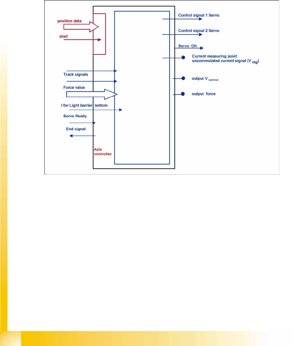
4.4.2 Axis Dynamic Basics
Each axis starts from a position with acceleration a constant speed phase and deceleration should move
the axis into a target position. The dynamic movement of the axis on the SIPLACE machine is regulated
by a digital control system. A powerful digital processor permanently adjusts the axis behavior to each
state of axis dynamic. This means all adjustments for speed (Tacho) and positioning quality (P-gain) at
the servo amplifier are removed. The control signals are different for this new axis control principle.
4-33: Digitally controlled axes for SIPLACE machine
Communication and Control
Axis Dynamic Basics Axis Control
Student Guide (FSE) SIPLACE X Series and X4I
Edition 01/2009 EN Communication and Control
133
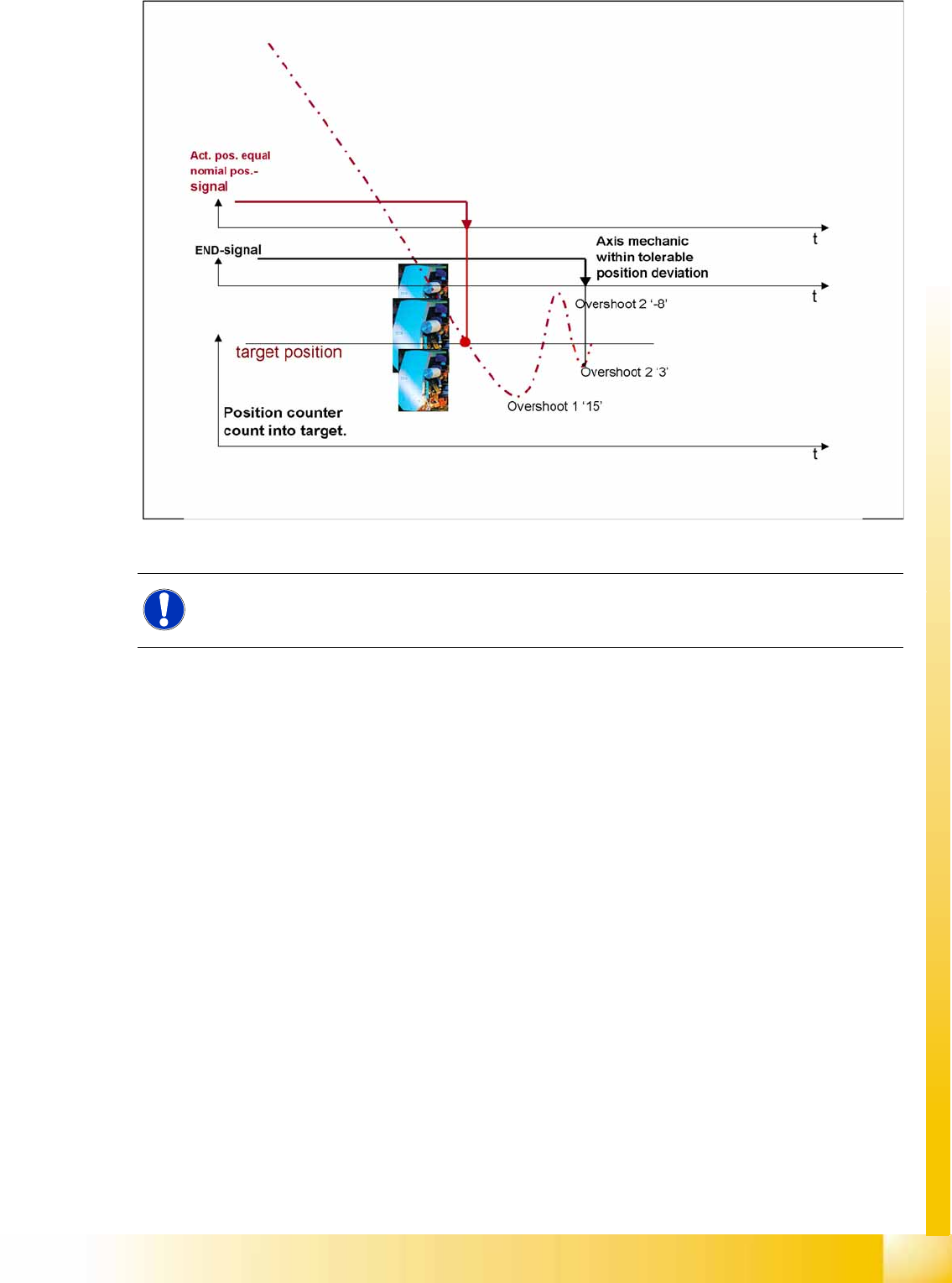
4-34: Positioning with overshoot into target position
During initial Positioning into the target position, the actual equals target position signal triggers an
overshoot count in the axis test box (SAT) for the position deviation signal.
If the overshoot is greater than the permitted position deviation for this axis, the end position signal will
be delayed until the deviation has been regulated so that it is within the permitted range.
NOTE:
The position deviation signal shows the positioning quality of an axis movement in position.