00196044-05 - sg x und x4i fse_en.pdf - 第135页
Communication and Control Axis Dynamic Basics Axis Control S tudent Guide (FSE) SIPL ACE X Series and X4I Edition 01/2009 EN Communication and Control 135 The uncommutated target cur rent signal is an envel ope signal fo…
Communication and Control
Axis Control Axis Dynamic Basics
Student Guide (FSE) SIPLACE X Series and X4I
Communication and Control Edition 01/2009 EN
134
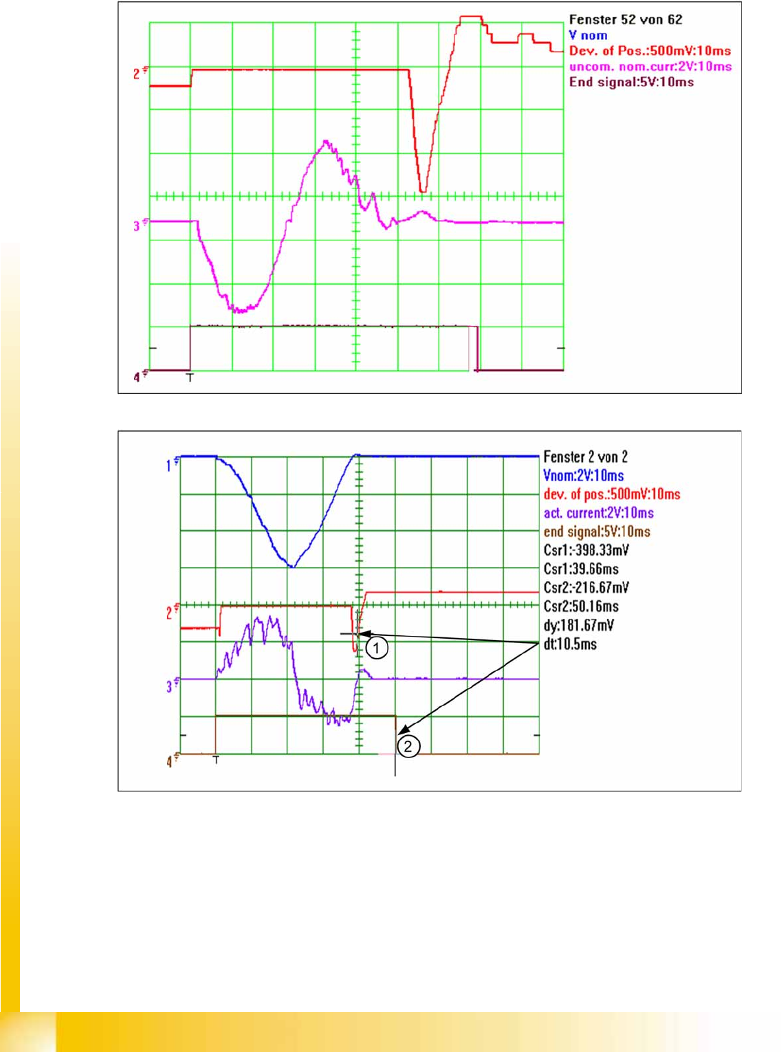
4-35: The 2nd overshoot sets the end signal
4-36: Positioning with asymptotic approach after the initial, excessive overshoot
The positioning shown above demonstrates an excessive overshoot. However, no other overshoot, for
which an end signal could be issued, will occur during this positioning run. The axis controller has a
’backup strategy’ - When the permitted position deviation range is reached, a 10ms timer is started. 10
ms after entering the permissible range (here 5 digits (1)) the timer triggers the end position signal (2).
The permitted range must not be left during this period.
The system generates an uncommutated current target signal from all motor current target signals for
assessment of the axis dynamics by a service technician. This signal gives information about the
mechanical friction in the axis system. This can be measured on the adapter board of the axis test box
or at the Vreg output of the SIPLACE axis tester (SAT).
Communication and Control
Axis Dynamic Basics Axis Control
Student Guide (FSE) SIPLACE X Series and X4I
Edition 01/2009 EN Communication and Control
135
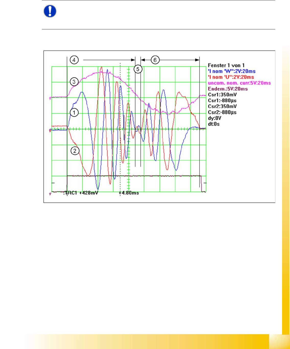
The uncommutated target current signal is an envelope signal for the 2 visible motor current target
signals from the axis controller. The 3rd motor current target signal (not visible) is calculated on the servo
amplifier board.
The known V nominal (Vnom) speed signal and the force signal have been replaced by the motor
current nominal signals for DC or AC drives.
4-37: The uncommutated motor current nominal signal (3) and the motor current signals (1) (2) of an AC motor
The acceleration section can be recognized in the motor current nominal signal of the AC motor (4) due
to the high amplitudes needed to supply the axis mechanics with sufficient force. The frequency of this
signal section is low, due to the low speed. The amplitude becomes lower and lower because the
necessary motor force is reduced with increasing speed.
The frequency increases as the speed of the motor rises, up to the maximum frequency for maximum
axis speed (5).
In the deceleration section, the amplitude increases again, to reduce the speed of the axis mechanics.
The frequency decreases, as does the speed of the axis (6). Finally, the axis is moved into the correct
target position, with overshoot control.
So there is nothing to adjust all this axes have a dynamic behavior. Each axis has friction to master. The
greater the friction is, the higher the amplitudes will be for acceleration and constant speed. The higher
motor force for acceleration and constant speed can be seen by the uncommutated motor current target
signal. Greater friction reduces the motor force required during the deceleration phase, making the
amplitude of the uncommutated motor current target signal smaller.
NOTE:
These motor current signals can be measured at the V nominal and the Force output of the
axis tester. The same signals are measurable at the 2 uppermost test pins on the servo amplifier
board, as Inom. U’ and Inom. W signals.
Communication and Control
Axis Control Axis Dynamic Basics
Student Guide (FSE) SIPLACE X Series and X4I
Communication and Control Edition 01/2009 EN
136
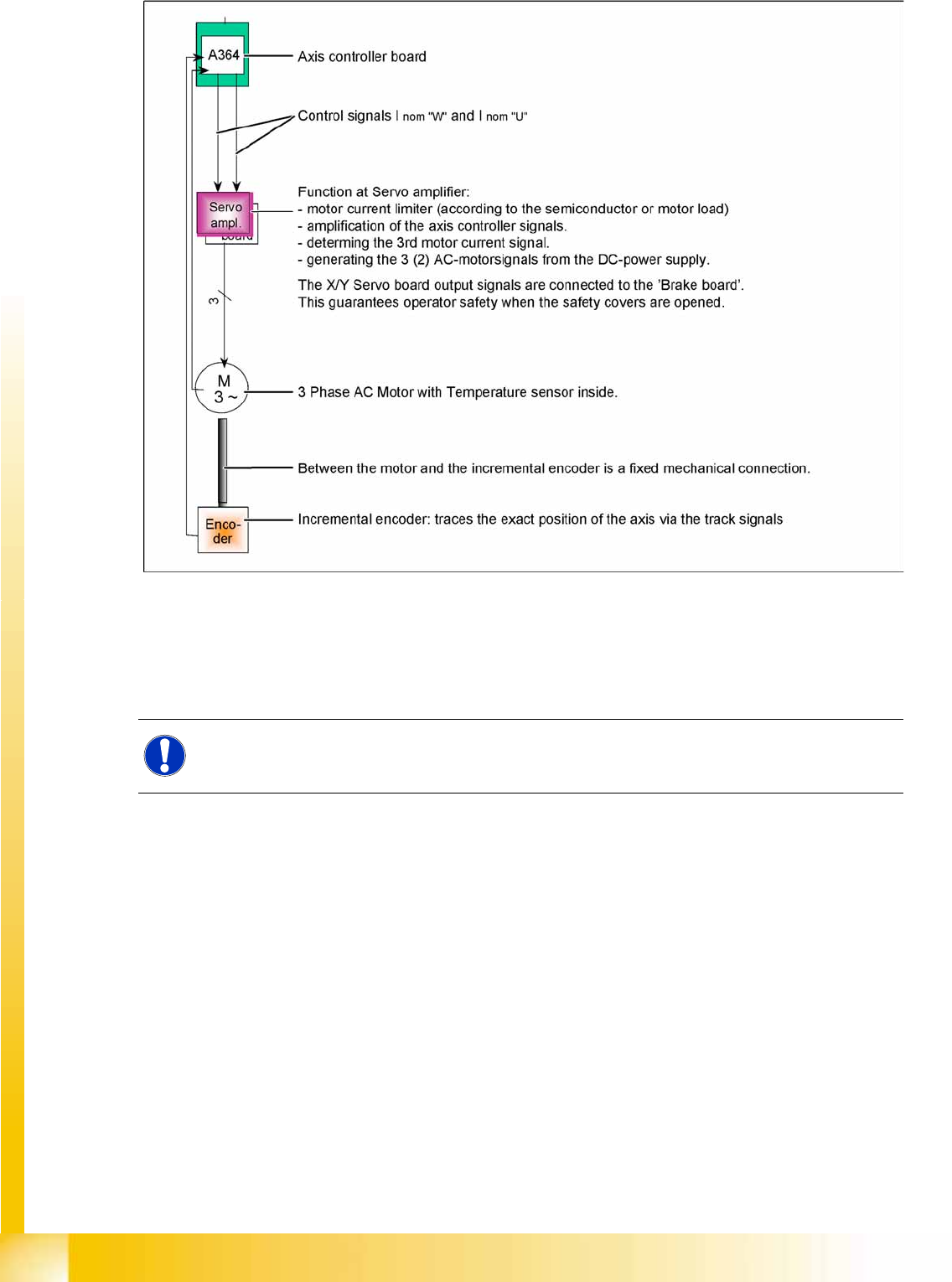
4-38: Axis block diagram, showing X or Y axis of SIPLACE X machine as example
Although the various axis types differ in details, all control tasks are handled by the axis controller. 2
control signals for 2 or 3 phase axis drive. For DC-drives we use the same hardware principle with only
1 control signal to the Servo amplifier. The only feedback is provided by the track signals from the
incremental encoder to the axis controller - a tacho (Z/DP axis) is not connected to the axis system.
See also:
J
4.4.2 Axis Dynamic Basics [
J
132]
NOTE:
Mechanical and electrical faults can be detected by analyzing the axis controller signal paths.