00196044-05 - sg x und x4i fse_en.pdf - 第137页
Communication and Control Axis controller Axis Control S tudent Guide (FSE) SIPL ACE X Series and X4I Edition 01/2009 EN Communication and Control 137 4.4.3 Axis controller 4.4.3.1 Axis Controller A364 4-39: View of the …
Communication and Control
Axis Control Axis Dynamic Basics
Student Guide (FSE) SIPLACE X Series and X4I
Communication and Control Edition 01/2009 EN
136
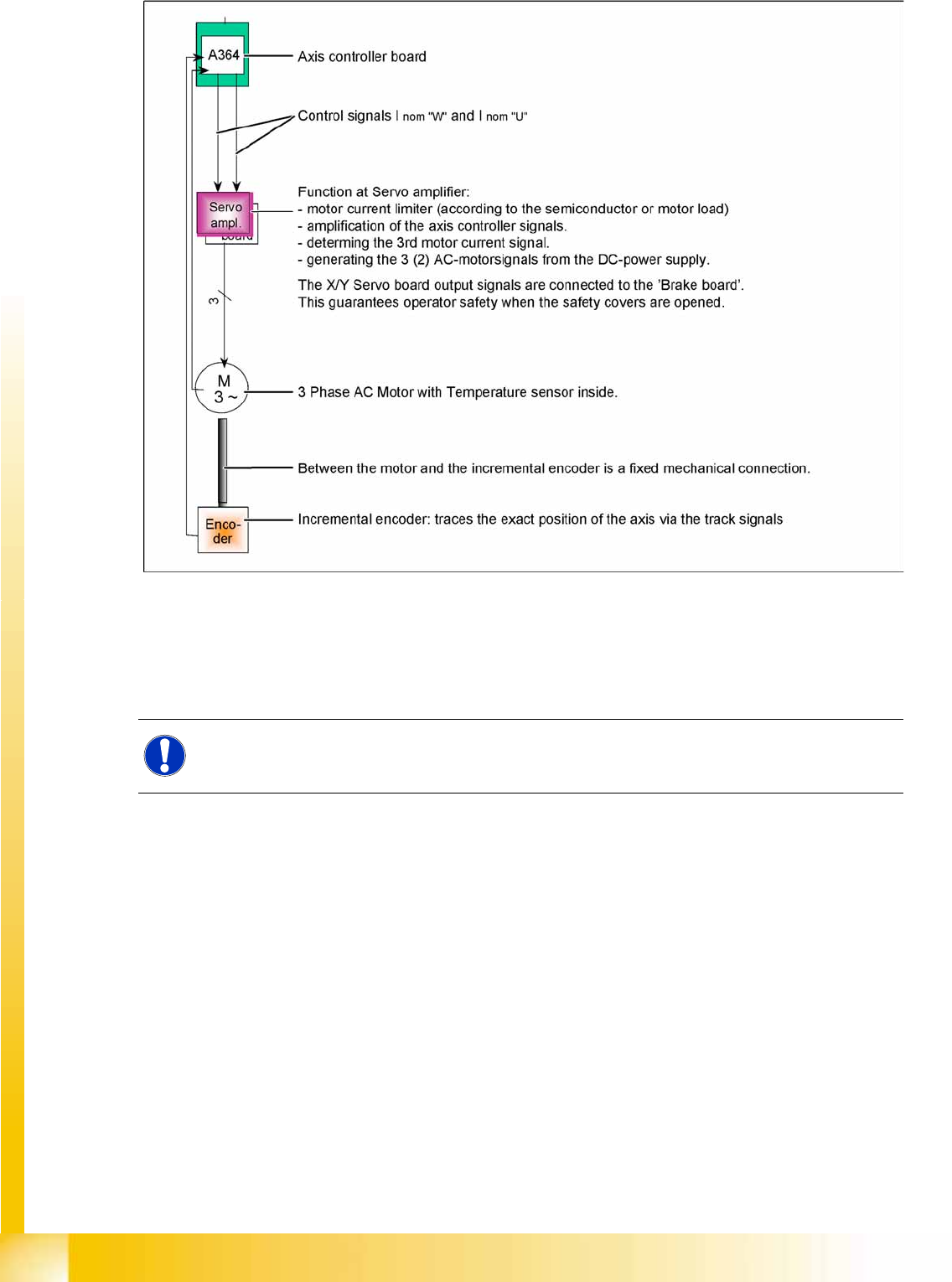
4-38: Axis block diagram, showing X or Y axis of SIPLACE X machine as example
Although the various axis types differ in details, all control tasks are handled by the axis controller. 2
control signals for 2 or 3 phase axis drive. For DC-drives we use the same hardware principle with only
1 control signal to the Servo amplifier. The only feedback is provided by the track signals from the
incremental encoder to the axis controller - a tacho (Z/DP axis) is not connected to the axis system.
See also:
J
4.4.2 Axis Dynamic Basics [
J
132]
NOTE:
Mechanical and electrical faults can be detected by analyzing the axis controller signal paths.
Communication and Control
Axis controller Axis Control
Student Guide (FSE) SIPLACE X Series and X4I
Edition 01/2009 EN Communication and Control
137
4.4.3 Axis controller
4.4.3.1 Axis Controller A364
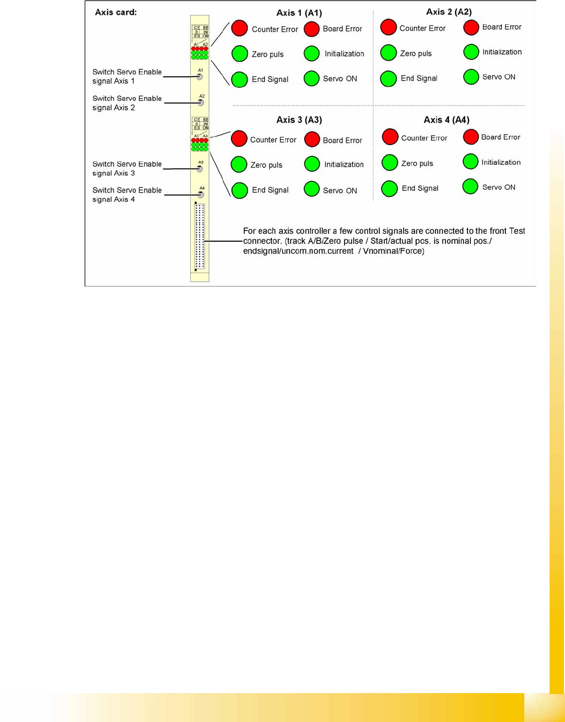
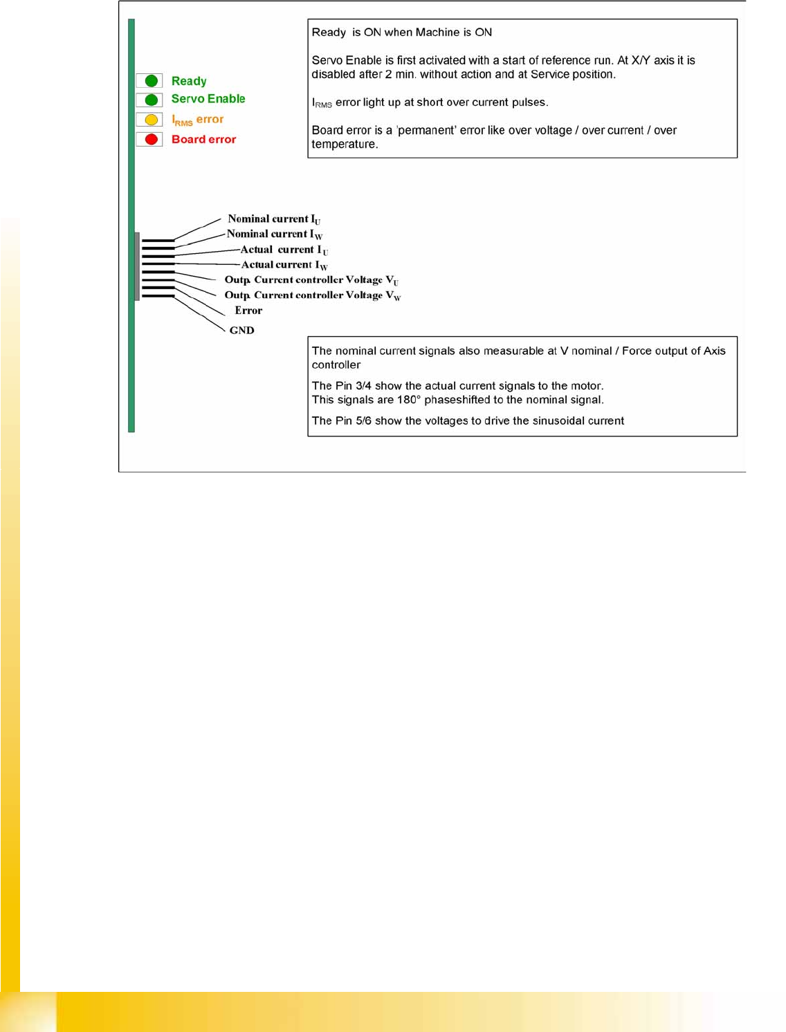
4-39: View of the SIPLACE machine axis controller A364 and its test signals
The axis controller receives the target position and the start signal from the station computer. All relevant
calculations and control actions are performed by the axis controller.
The axis controller A364 in the SIPLACE machine is socket coded. This means that the address
switches do not need to be set when parts are replaced.
The communication and axis control functions are handled by the axis controller.
The following is loaded for this purpose:
BIOS SW and
Firmware for the axis controller (application 1 and 2).
Because of the different types of drives and their control systems, this axis firmware version may differ.
This means the axis controller can not simply be plugged into a different position (slot) in the axis unit.
After replacing an axis controller, perform a download for the correct firmware.
Communication and Control
Axis Control Axis controller
Student Guide (FSE) SIPLACE X Series and X4I
Communication and Control Edition 01/2009 EN
138
4.4.3.2 Servo Amplifier TBS .. and SDS ...
4-40: Servo amplifier
Servo amplifiers of type TBS are used for the X/Y and star axes, while SDS servo amplifiers are used
for the Z and DP axes.
These SDS and TBS servo amplifiers can be reset with the servo disable/enable switch on the axis
controller board.
All servos are individually set for the maximum motor current of the drive unit connected. This mean that
the servo amplifiers need to be used on an axis-specific basis.
Measurement Pin MP7:
In the event of an error on the servo amplifier, you can measure various voltages at the analog output
pin MP7, to determine the error.
Overvoltage -1 V
Overcurrent -2 V
Overtemperature -3 V
Nominal current exceeded -4 V