00196044-05 - sg x und x4i fse_en.pdf - 第155页
Communication and Control One Wire Bus SIPLACE X Machine One Wire Bus S tudent Guide (FSE) SIPL ACE X Series and X4I Edition 01/2009 EN Communication and Control 155 4.5.3.2 Overview of One Wire Bus Initialization Legend…
Communication and Control
One Wire Bus One Wire Bus SIPLACE X Machine
Student Guide (FSE) SIPLACE X Series and X4I
Communication and Control Edition 01/2009 EN
154
4.5.3 One Wire Bus SIPLACE X Machine
The structure of the SIPLACE X and X4I machines has been changed. This results in a different
hardware structure of the bus system and the subsystems to the hardware components.
During the initialization procedure, the subsystems independently log themselves on to the one wire bus
via the public byte. The public byte is sent via the CAN ID +3hex of the relevant subsystem. If the state
of a subsystem changes, the subsystem reports automatically and without a request from the
application.
See also:
J
Allocation of Subsystems to the Hardware Components [
J
147]
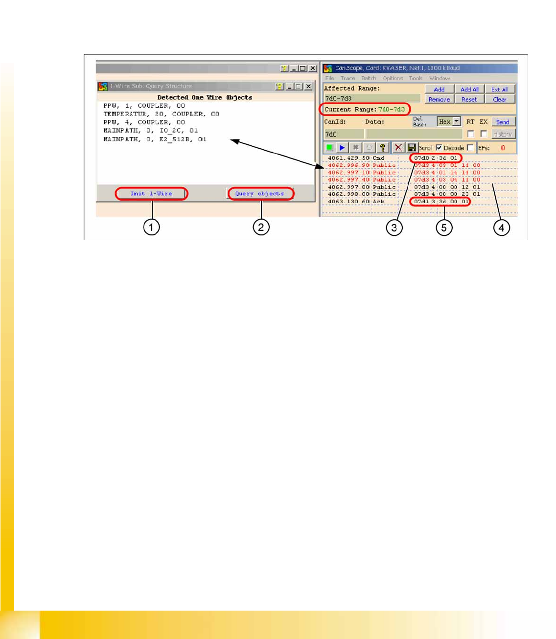
4.5.3.1 One Wire Communication
4-54: Communication with the one wire interface RS232 on the I/O module
Legend
1.
Init 1 Wire
sends the command via the CAN ID
7d0
(PA1)
2.
Query objects
shows the decoded public bytes.
3. Net window:
07d0 3d 01
Command initialization for the one wire bus.
4. 5 public bytes from subsystem 1-Wire CAT5 interface on the I/O module
1.
03 01 1f 00
-->
03
Subsystem NC /
01
Gantry /
1f
Coupler
2.
01 14 1f 00
-->
01
Subsystem temperature gantry 1/4 /
14
1k EEPROM /
1f
Coupler
3.
03 04 1f 00
-->
03
Subsystem NC /
04
Gantry /
1f
Coupler
4.
00 00 12 01
-->
12
I/O component and EEPROM
5.
00 00 23 01
-->
23
4k EEPROM
5. Acknowledge (Ack) command CAN ID +1hex -->
3d 00 01
Communication and Control
One Wire Bus SIPLACE X Machine One Wire Bus
Student Guide (FSE) SIPLACE X Series and X4I
Edition 01/2009 EN Communication and Control
155
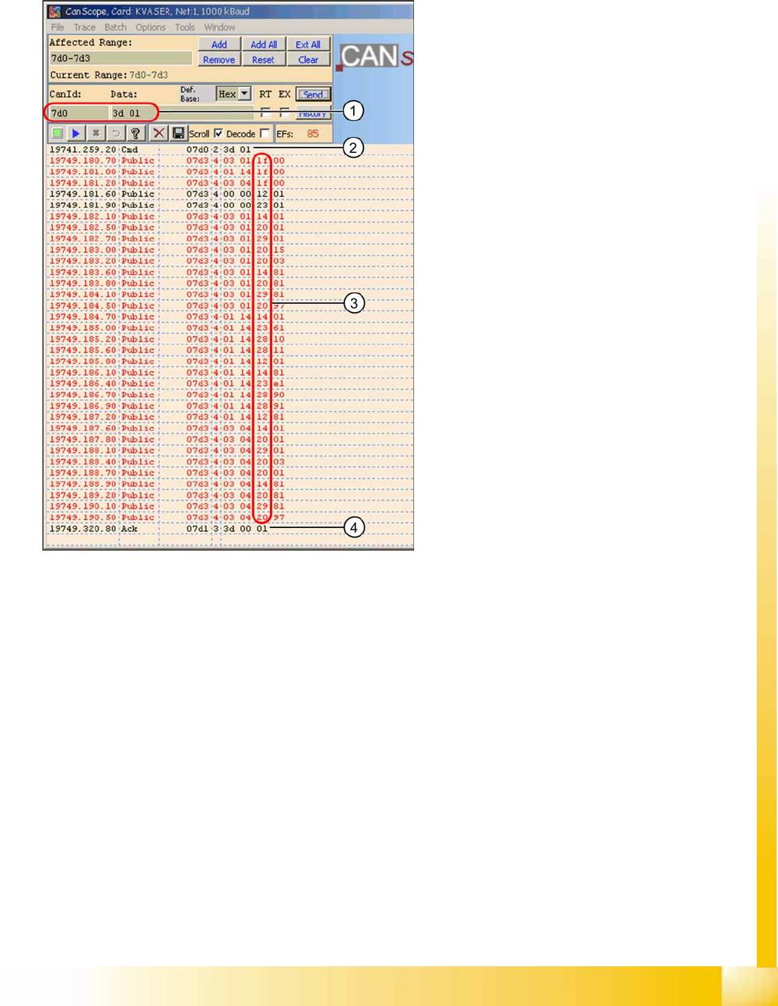
4.5.3.2 Overview of One Wire Bus Initialization
Legend
1. CAN BUS command for initialization
2. CAN BUS command sent.
3. Subsystems report, public bytes
1f
--> Coupler
12
--> IO component with EEPROM
14
--> 1k EEPROM
20
--> 4 channel A/D
23
--> 4k EEPROM
28
--> Temperature
29
--> 8-fold IO component
4. Ack initialization successful.

Communication and Control
Board IDs What are Board IDs?
Student Guide (FSE) SIPLACE X Series and X4I
Communication and Control Edition 01/2009 EN
156
4.6 Board IDs
4.6.1 What are Board IDs?
The board ID is an identification number, which is saved in an EEPROM. These ID‘s identify the boards
(head interface, head adapter,...) in the machine via software. Each board which communicates with a
TQM module, has an EEPROM with a unique ID. These board IDs are read and checked by the BIOS
in the TQM module.
4.6.1.1 Why Have We Introduced Board IDs?
The introduction of board IDs has the benefit that only one BIOS version can be used for all TQM
modules in the machine.
Benefits:
Simple to use for developers, setup engineers and service engineers
Updates by developers only required for one BIOS version
Storage, one SAP number for TQM modules (16 bit processor)
The introduction of one BIOS version on the TQM Modules, for the different subsystems, was necessary
for the option Head Modularity.
4.6.1.2 Function
During the booting phase, the TQM module BIOS sends a request for the board ID and thereby
recognizes which boards are connected for the placement head used or on which board the TQM
module is used. If all IDs are recognized and if they are all plausible, the application software will be
loaded. From SW 601.02, the station software issues an error message, if it does not recognize any of
the IDs or if it there is no plausible ID. This error message is currently only shown on the 7-segment
display of the TQM module.
4.6.1.3 Error Description for Missing IDs:
When the BIOS and Application software are downloaded and the BIOS is unable to recognize one ID,
it will give an error on the seven segment display for a short time. The error message appears three
times, after that the application software starts up. The machine still starts up and can produce. If the
BIOS is unable to recognize more than one ID, the TQM module in the BIOS stops with an error code
on the 7 segment display. The machine will not boot and an error message will appear at the station and
on the 7-segment display of the TQM module (see error list).
The following ID‘s are saved in the PCB‘s EEPROM:
NOTE:
Board IDs have nothing to do with the recognition of boards by the
PCB barcode
option.