00196044-05 - sg x und x4i fse_en.pdf - 第165页
Communication and Control Troubleshooting If Two Board Type IDs a re Missing Board I Ds S tudent Guide (FSE) SIPL ACE X Series and X4I Edition 01/2009 EN Communication and Control 165 X (4) Select Send . X (5) Command wi…
Communication and Control
Board IDs Reading the Board IDs out of the EEPROM
Student Guide (FSE) SIPLACE X Series and X4I
Communication and Control Edition 01/2009 EN
164
X Perform a BIOS download to the TQM module, so that you are sure that only the BIOS is running.
X Open the network 1 for PA 1 and network 2 to for PA 2.
X With the correct CAN ID and the BIOS commands, you can now write the correct board ID in the
EEPROM.
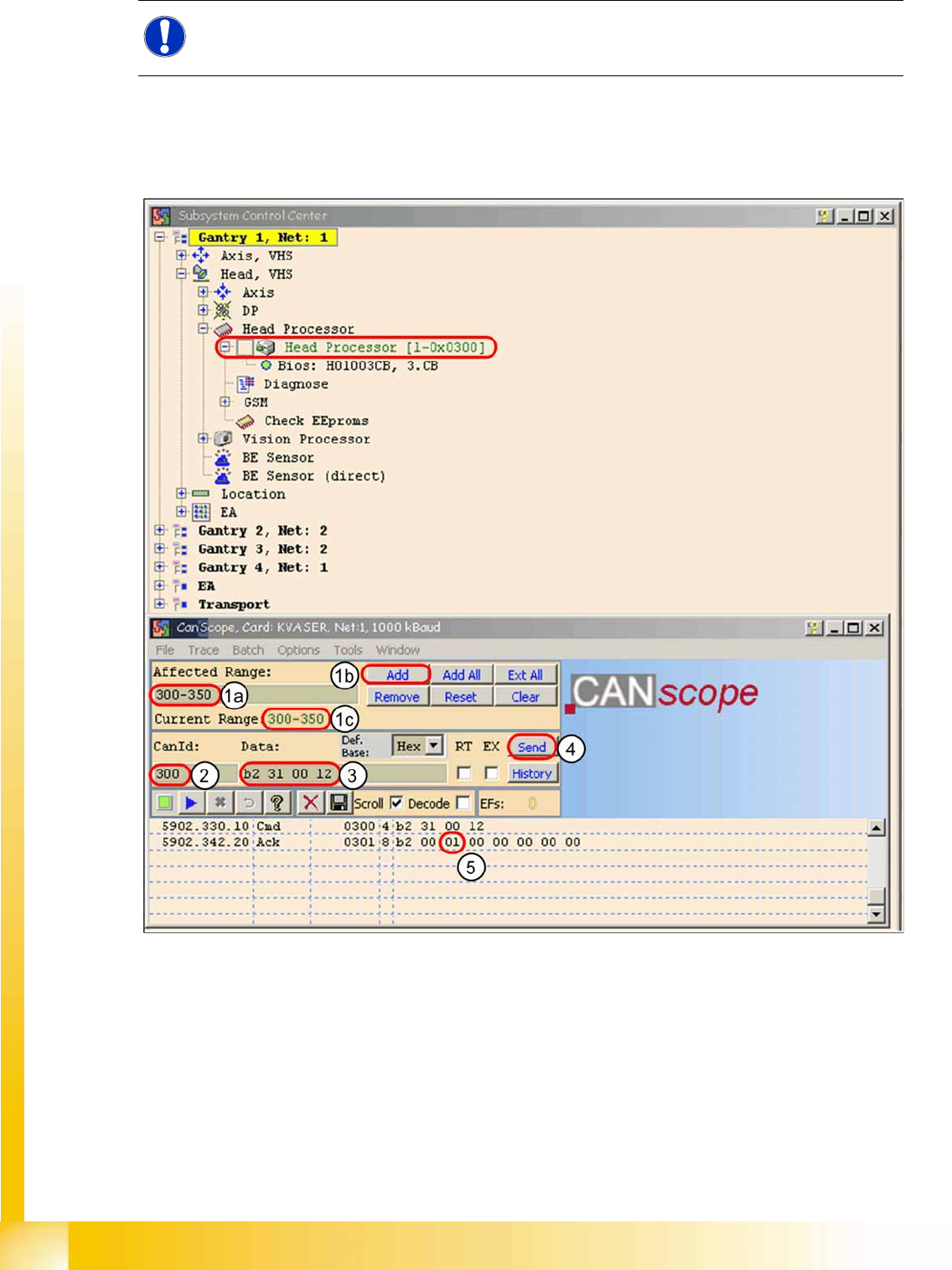
4-67: Read the board type ID Head interface
X (1) Restrict the address range for the CAN ID. Specify the smallest possible range at
Affected Range
, This reduces the number of CAN telegrams shown in the network window.
X Confirm with
Add
X The CAN ID range will now be shown at
Current Range
.
X (2) At
CanID
enter the relevant ID.
X (3) At
Data
enter the CAN command.
Example
B2 31 00 12
b2
--> read EEPROM
31
--> read out from head interface
12
--> Storage location in EEPROM memory in hex
NOTE:
To write the board IDs with CAN commands, make sure that just the BIOS is running on the
TQM module.
Communication and Control
Troubleshooting If Two Board Type IDs are Missing Board IDs
Student Guide (FSE) SIPLACE X Series and X4I
Edition 01/2009 EN Communication and Control
165
X (4) Select
Send
.
X (5) Command will be shown in the network window and an answer will be sent (acknowledge).
Ack
B2 00 01 00 00 00 00 00
--> Storage location 12 is occupied with the value
01
= board ID head
interface.
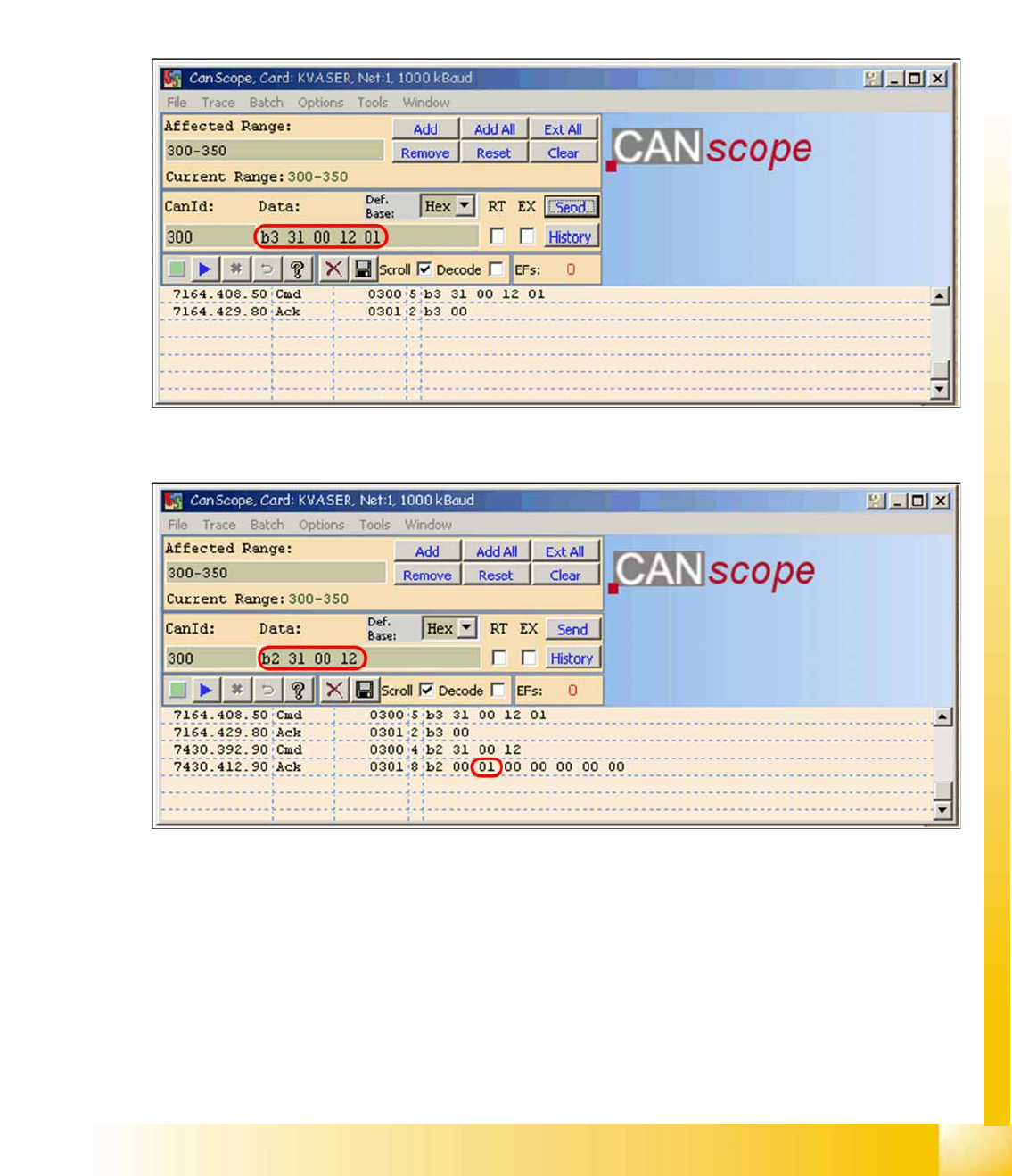
X Write the correct board ID with the command
B3 31 00 12 01
B3
--> write to EEPROM
31
--> head interface
12
--> storage location in EEPROM
01
--> board ID for head interface
Ack
B3 00
--> command OK
4-68: Writing the CAN command board ID on the head interface
X Check the board type ID after you written the ID in the EEPROM
4-69: Check the written board type ID
X Download the applications software on the TQM module.
> After performing the download, the TQM module should load again without error messages.
4.6.3 Troubleshooting If Two Board Type IDs are Missing
If two IDs are missing, preventing the machine (TQM module) from booting, use the default CAN ID to
address the TQM module on the head processor (CAN ID +4hex) (see Section (4.6.2.2 Reading and Wri-
ting the Board IDs with CAN Commands
J
163 ) ).

Communication and Control
Board IDs CAN Commands for Reading and Writing the Board IDs
Student Guide (FSE) SIPLACE X Series and X4I
Communication and Control Edition 01/2009 EN
166
4.6.4 CAN Commands for Reading and Writing the Board IDs
Applicable for SIPLACE X and SIPLACE D machines.
NOTE:
To write the board IDs with CAN commands, make sure that just the BIOS is running on the
TQM module.
Read out the
board type ID
from the
EEPROM:
(Example on gantry 1 CAN ID
300
on C&P20A)
CAN ID:
300
Cmd:
B2 31 00 12
read head interface
CAN ID:
301
Ack:
B2 00 01 00 00 00 00 00
board ID 01
CAN ID:
300
Cmd:
B2 32 00 12
read head adapter
CAN ID:
301
Ack:
B2 00 22 00 00 00 00 00
board ID 22
CAN ID:
300
Cmd:
B2 33 00 12
read intermediate distributor
CAN ID:
301
Ack:
B2 00 30 00 00 00 00 00
board ID 30
CAN ID:
300
Cmd:
B2 34 00 12
read digital pressure control valve
CAN ID:
301
Ack:
B2 00 00 00 01 00 00 00
Board ID 00 not defined
(memory location 14 = assembly ID
01
is digital pressure control valve)
CAN ID: 300 Cmd:
B2 35 00 12
read vacuum sensor holding circuit
CAN ID: 301 Ack:
B2 00 31 00 00 00 00 00
Board ID 31
e.g. Gantry 1
Vision Board:
CAN ID:
180
Cmd:
B2 11 00 12
read Vision board
CAN ID:
181
Ack:
B2 00 11 00 00 00 00 00
Board ID 11
e.g. Gantry 3
Vision Board
stationary:
CAN ID:
150
Cmd:
B2 11 00 12
read Vision board, stationary
CAN ID:
151
Ack:
B2 00 12 00 00 00 00 00
Board ID 12
e.g. Gantry 3
pressure control
valve (analog)
Twin head:
CAN ID:
180
Cmd:
B2 36 00 12
read analog pressure control valve
CAN ID:
181
Ack:
B2 00 00 00 02 00 00 00
Board ID 00 not defined
(memory location 14= assembly ID 02 is analog pressure control valve)
Command 36 only functions if the TQM module is on the head interface.If the TQM module is
directly on the Twin head (main board, C600) you must use command 22.
EEPROM write:
(Example on gantry 1 CAN ID
300
on C&P20A)
CAN ID:
300
Cmd:
B3 31 00 12 01
write head interface board ID 01
CAN ID:
301
Ack:
B3 00
CAN ID:
300
Cmd:
B3 32 00 12 22
write head adapter board ID 22
CAN ID:
301
Ack:
B3 00
CAN ID:
300
Cmd:
B3 33 00 12 30
write intermediate distributor board ID 30
CAN ID:
301
Ack:
B3 00
CAN ID:
300
Cmd:
B3 35 00 12 31
write vacuum sensor holding circuit board ID 31
CAN ID:
301
Ack:
B3 00
e.g. Gantry 1
Vision Board:
CAN ID:
180
Cmd:
B3 11 00 12 11
write Vision board, board ID 11
CAN ID:
181
Ack:
B3 00
e.g. Gantry 3
Vision Board
stationary:
CAN ID:
150
Cmd:
B3 11 00 12 12
write Vision board stationary, board ID 12
CAN ID:
151
Ack:
B3 00