00196044-05 - sg x und x4i fse_en.pdf - 第179页
Energy and Compressed Air Supply Power supply Power supply S tudent Guide (FSE) SIPL ACE X Series and X4I Edition 01/2009 EN Energy and Compressed Air Supply 179 5.2.4.3 T ransformer 1 The main reason for the transfo rme…
Energy and Compressed Air Supply
Power supply Power supply
Student Guide (FSE) SIPLACE X Series and X4I
Energy and Compressed Air Supply Edition 01/2009 EN
178
5.2.4.2 Input Voltage
5-6: Input voltage
Legend
F11 Fuse (1A) inrush current
limitation board 1-phase
1, 2 33,6 VDC to GND
F12 Fuse (6 A)
illumination; 1-phase
1, 2 52 VDC to GND
F13 fuse (3A) monitor;
1-phase
1, 2 26 VDC to GND
F14 Fuse (6 A)
cooling device Y motor
1-phase
1, 2 24 VDC to GND
F21 / F22 /
F23
Micro fuse (T6,3A) discharge
inductor L20
1, 2 3 x 204 VAC / 3 x 380 VAC
3 x 400 VAC / 3 x 415 VAC
F61 / F62 fuse (10A) rectifier U4 1, 2 3 x 28 VAC
F81 / F82 Microfuse (T10A)
rectifier U5
1, 2 3 x 23.8 VAC
F111 / F112 Microfuse (T1A)
rectifier U8
1, 2 3x 25.7 (23.8V) VAC
F131 / F132 Microfuse (T4A)
rectifier U10
1, 2 3x 20.5 (19.7V) VAC
F141 / F142 Microfuse (T6,3A)
rectifier U11
1, 2 3x 18.9 (18.7V) VAC
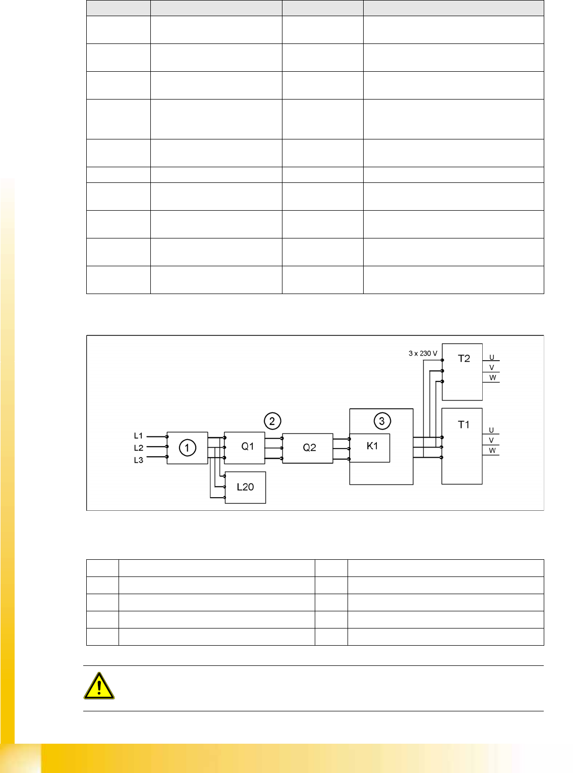
Assembly Designation Contact Voltages
1 Current filter K1 main contactor and inrush current limiter for T1
2 3 phases T1 transformer 1
3 Inrush current limitation board for T1 T2 Transformer 2
Q1 Main switch L20 Discharge inductor
Q2 Motor Circuit Breaker
ATTENTION:
After transformers T1 and T2, the main power potential ends and the machine is only fed by
secondary voltages.
Energy and Compressed Air Supply
Power supply Power supply
Student Guide (FSE) SIPLACE X Series and X4I
Edition 01/2009 EN Energy and Compressed Air Supply
179
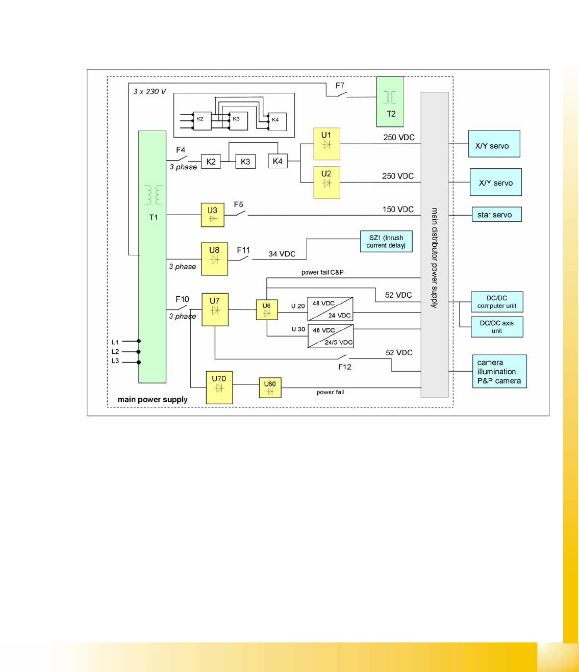
5.2.4.3 Transformer 1
The main reason for the transformer T1 is to power the X/Y and star axis, protected by F4. Contactors
K2, K3 and K4 illustrate fixed elements of the electrical safety concept. In a fault event, e.g. open cover,
the servos are disconnected from the energy.
Primary Transformer T1
250 VDC for the servo amplifiers of the x and y axes.
150 VDC servo amplifiers of the star axis.
34 VDC for the inrush current limiter servo
52 VDC for the DC/DC converters in the main power unit
48 VDC for DC/DC converter of camera illumination and the computer unit
5-7: Overview of main voltage supply and transformer
Energy and Compressed Air Supply
Power supply Power supply
Student Guide (FSE) SIPLACE X Series and X4I
Energy and Compressed Air Supply Edition 01/2009 EN
180
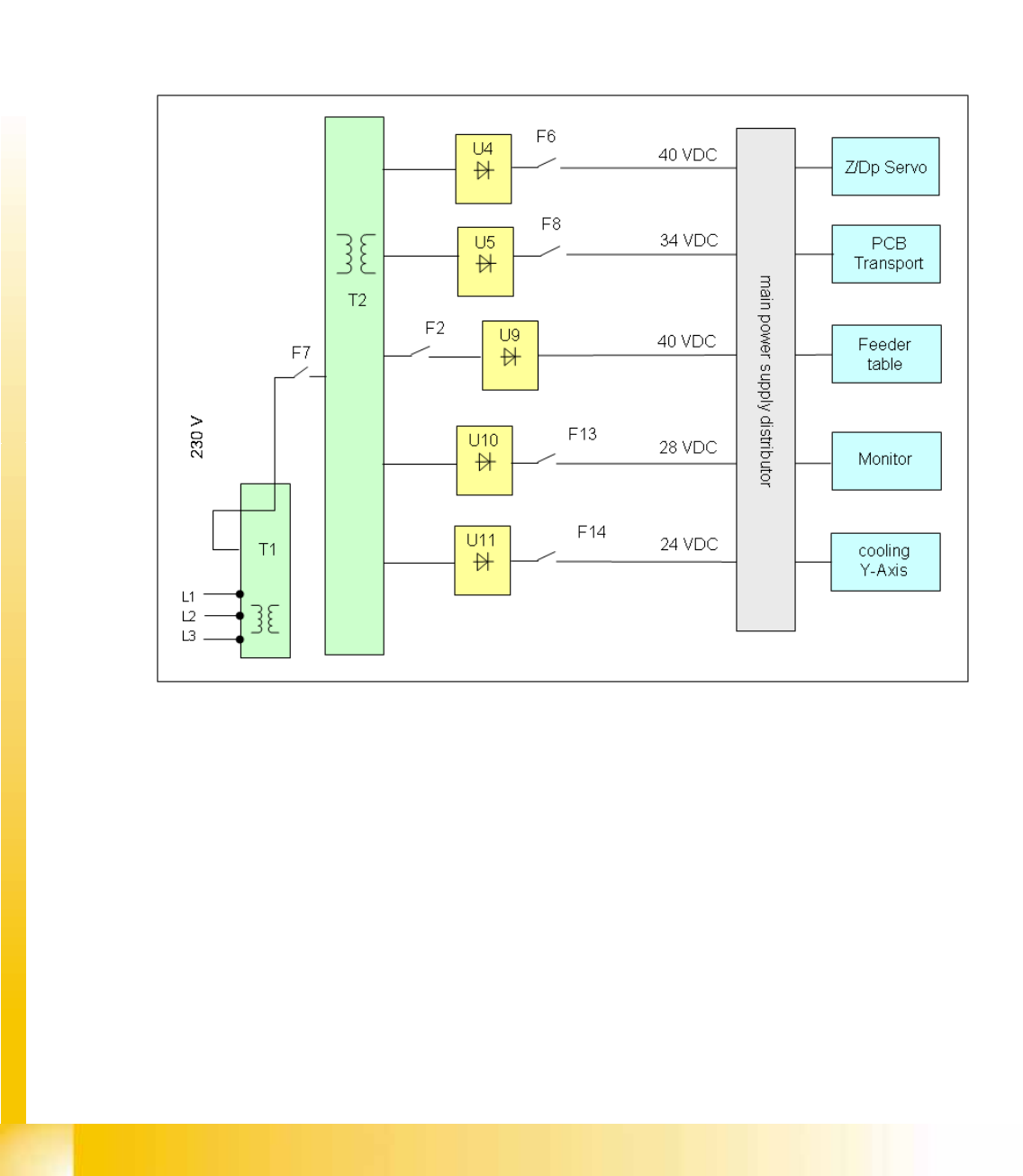
5.2.4.4 Transformer T2
The main task assumed by transformer T2 is to power the Z and DP servos, protected by F6.
Secondary transformer T2
40 VDC for the servo amplifiers the z and dp axes.
34 VDC for PCB handling system.
40 VDC for the component tables (30 V for feeder operation).
10 VDC for the component tables (5 V for logic).
28 VDC for the monitor.
24 VDC for cooling the Y axis motor. (motor generating compressed air)
5-8: Overview transformer 2