00196044-05 - sg x und x4i fse_en.pdf - 第180页
Energy and Compressed Air Supply Power supply Power supply S tudent Guide (FSE) SI PL ACE X Series and X4I Energy and Compres sed Air Supply Edition 01/20 09 EN 180 5.2.4.4 T ransformer T2 The main task assumed by transf…
Energy and Compressed Air Supply
Power supply Power supply
Student Guide (FSE) SIPLACE X Series and X4I
Edition 01/2009 EN Energy and Compressed Air Supply
179
5.2.4.3 Transformer 1
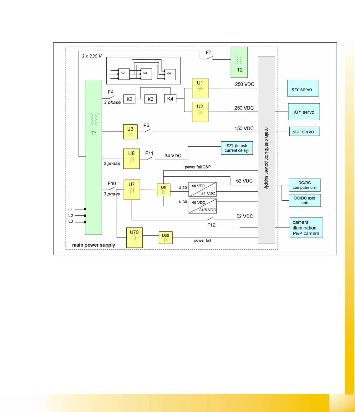
The main reason for the transformer T1 is to power the X/Y and star axis, protected by F4. Contactors
K2, K3 and K4 illustrate fixed elements of the electrical safety concept. In a fault event, e.g. open cover,
the servos are disconnected from the energy.
Primary Transformer T1
250 VDC for the servo amplifiers of the x and y axes.
150 VDC servo amplifiers of the star axis.
34 VDC for the inrush current limiter servo
52 VDC for the DC/DC converters in the main power unit
48 VDC for DC/DC converter of camera illumination and the computer unit
5-7: Overview of main voltage supply and transformer
Energy and Compressed Air Supply
Power supply Power supply
Student Guide (FSE) SIPLACE X Series and X4I
Energy and Compressed Air Supply Edition 01/2009 EN
180
5.2.4.4 Transformer T2
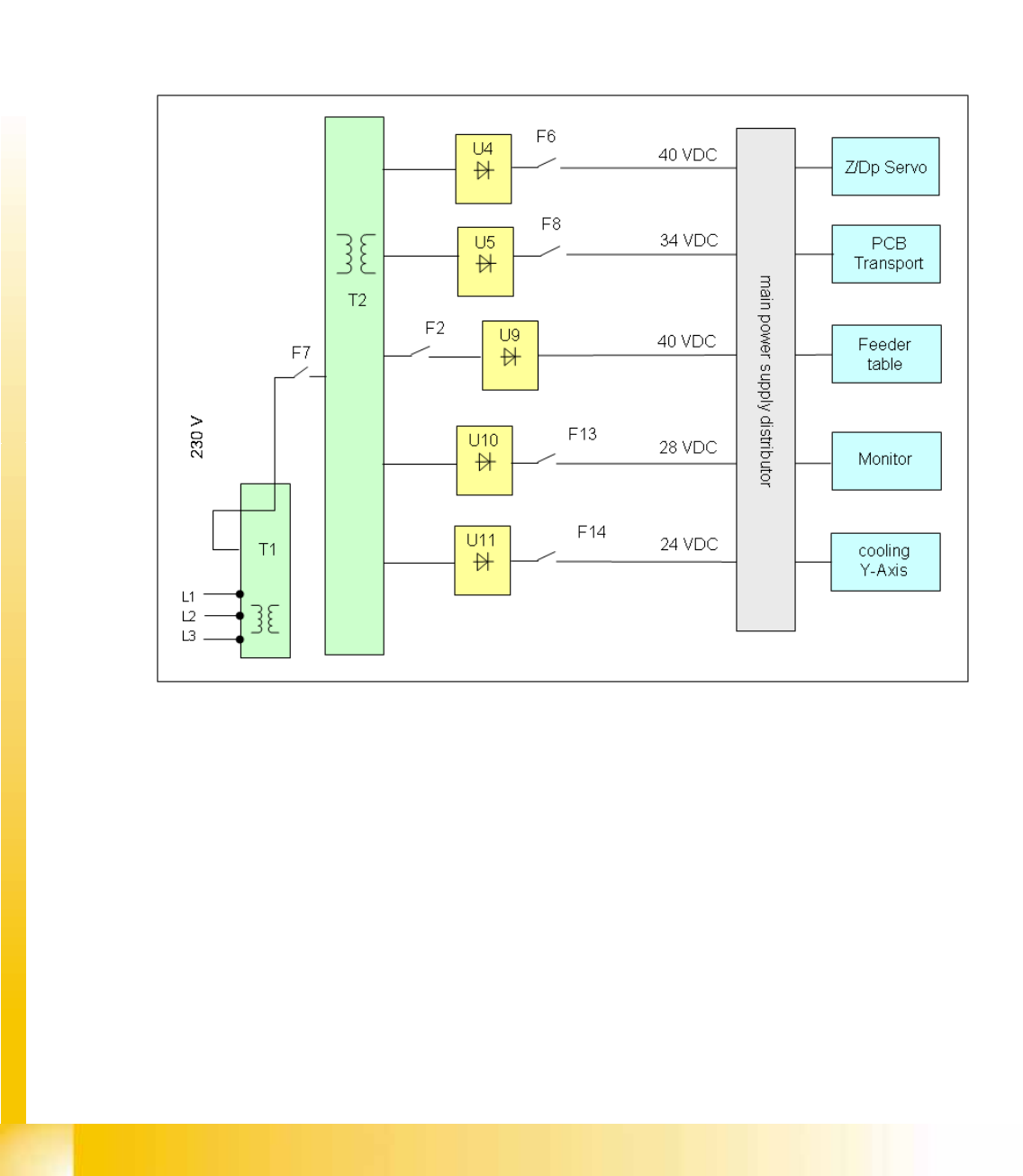
The main task assumed by transformer T2 is to power the Z and DP servos, protected by F6.
Secondary transformer T2
40 VDC for the servo amplifiers the z and dp axes.
34 VDC for PCB handling system.
40 VDC for the component tables (30 V for feeder operation).
10 VDC for the component tables (5 V for logic).
28 VDC for the monitor.
24 VDC for cooling the Y axis motor. (motor generating compressed air)
5-8: Overview transformer 2
Energy and Compressed Air Supply
Power supply Power supply
Student Guide (FSE) SIPLACE X Series and X4I
Edition 01/2009 EN Energy and Compressed Air Supply
181
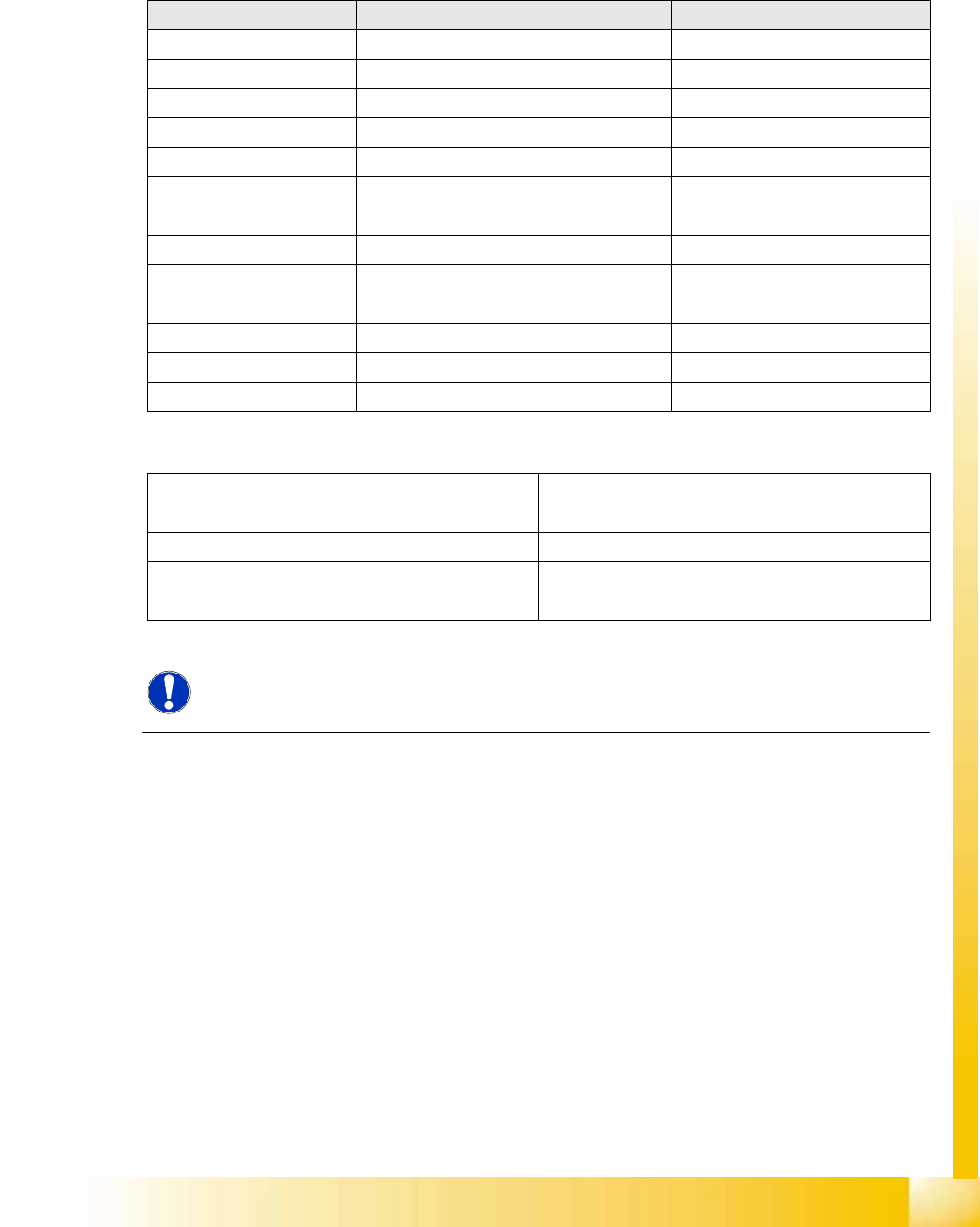
5.2.4.5 Voltages in the Power Supply Unit After Switching On
When the main switch is switched on, the following voltages are generated and may or may not be
switched (enabled, not enabled) through to the modules:
Voltages for the service socket
Voltages Module State
250 VDC X/Y servo unit not enabled
150 VDC servo unit not enabled
34 VDC PCB handling system not enabled
24 VDC tape cutter not enabled
34 VDC SZ1 main power inrush current enabled
52 VDC DC/DC converter main power supply enabled
48 VDC Illumination for all cameras enabled
52 VDC Supply to power fail board enabled
40 VDC Z/DP axes enabled
40 VDC Changeover table enabled
28 VDC monitor enabled
24 VDC fan enabled
230 or 115 or 240 VAC Service socket Independent of the main switch
230 VAC (Europe) Input 3 x 400 VAC
115 VAC (U. S. A.) Input 3 x 204 VAC
130 VAC (other) Input 3 x 230 VAC
220 VAC (other) Input 3 x 380 VAC
240 VAC (other) Input 3 x 415 VAC
NOTE:
The service socket can only be used if the placement system is connected to the main power
supply with a 5-conductor cable (L1, L2, L3, N, PE).