00196044-05 - sg x und x4i fse_en.pdf - 第188页
Energy and Compressed Air Supply Power supply Safety and Signaling Circuit S tudent Guide (FSE) SI PL ACE X Series and X4I Energy and Compres sed Air Supply Edition 01/20 09 EN 188 5.2.8.2 Control Loop s Changeover T abl…
Energy and Compressed Air Supply
Safety and Signaling Circuit Power supply
Student Guide (FSE) SIPLACE X Series and X4I
Edition 01/2009 EN Energy and Compressed Air Supply
187
5.2.8 Safety and Signaling Circuit
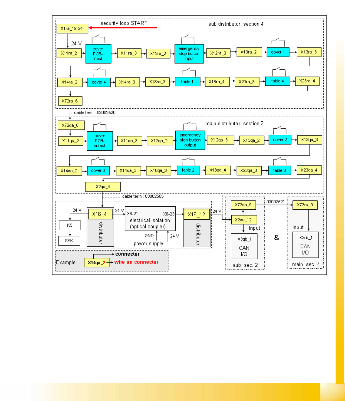
5.2.8.1 Emergency STOP Circuit (Safety Circuit)
Following contacts are switched in serial and build the safety loop:
4 protective cover switches (main cover).
conveyor cover switch.
Contact on changeover table
The emergency STOP button may not be pressed (input and output conveyors)
5-14: Safety loop
Description of emergency STOP circuit:
When the emergency STOP circuit is closed, there is 24 V present at K5, contact 3. A further 24 V signal
is sent as
EMERGENCY STOP loop OK
Sent to each CAN I/O module, indicating that the covers are
all closed and that the changeover tables are connected.
Energy and Compressed Air Supply
Power supply Safety and Signaling Circuit
Student Guide (FSE) SIPLACE X Series and X4I
Energy and Compressed Air Supply Edition 01/2009 EN
188
5.2.8.2 Control Loops
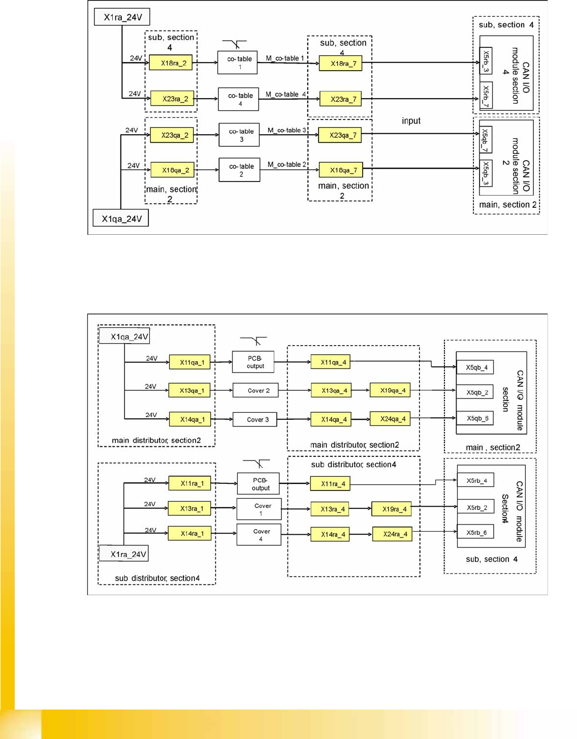
Changeover Table Loop
5-15: Changeover table loop
The 4 component tables are switched in parallel mode. If one or more tables are not connected, the
contact will close and 24 V will be present at the input of the CAN I/O module in sector 2 or 4.
Cover Control Loop
5-16: Cover Control Loop
The cover control loop consists of 6 contacts (2 main covers, each with 2 contacts and 2 covers on the
conveyors (input and output)), which are switched in parallel mode. If 1 or more covers are open, the
contact will close and the 24 V will be present at the input of the CAN I/O module in sector 4. The same
applies to sector 2. This shows that one of the covers is open.
Energy and Compressed Air Supply
Safety and Signaling Circuit Power supply
Student Guide (FSE) SIPLACE X Series and X4I
Edition 01/2009 EN Energy and Compressed Air Supply
189
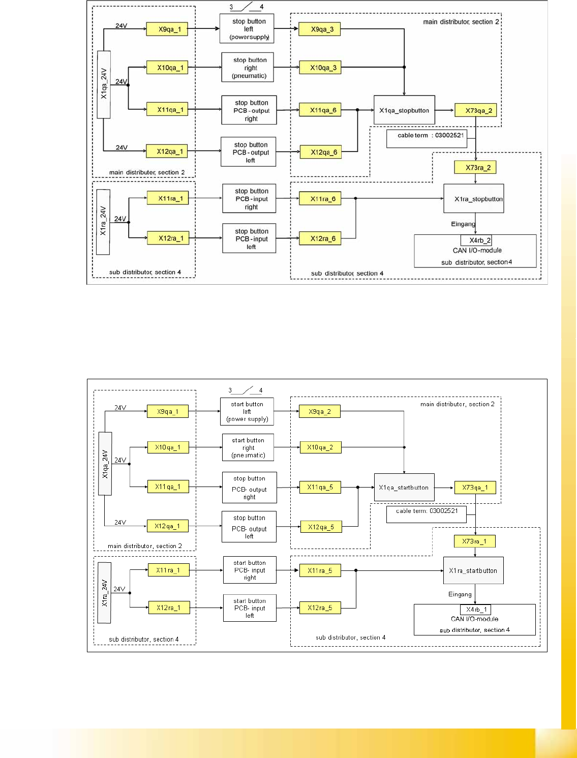
Stop Button Loop
5-17: Stop Button Loop
The stop button loop consists of 6 contacts which are switched in parallel mode. If one or more STOP
buttons has been pressed, the contact will close and 24 V will be present at the input of the CAN I/O
module in sector 4, showing that one of the STOP buttons has been pressed.
Start Button Loop
5-18: Start Button Loop
The start button loop consists of 6 contacts and they are switched in parallel mode. If one or more START
buttons has been pressed, the contact will close and the 24 V will be present at the input of the CAN I/
O module in sector 4, showing that one of the START buttons has been pressed.