00196044-05 - sg x und x4i fse_en.pdf - 第198页
Energy and Compressed Air Supply Pneumatic System Overview Pneumatic System S tudent Guide (FSE) SI PL ACE X Series and X4I Energy and Compres sed Air Supply Edition 01/20 09 EN 198 5.3.2 Overview Pneumatic System The co…

Energy and Compressed Air Supply
Pneumatic Unit Pneumatic System
Student Guide (FSE) SIPLACE X Series and X4I
Edition 01/2009 EN Energy and Compressed Air Supply
197
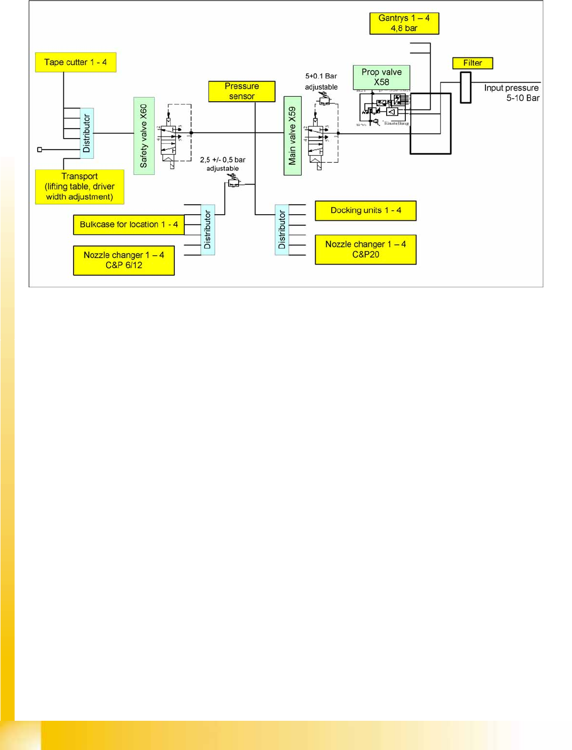
The input pressure (5-10 bar) flows through the compressed air filter. These need to be checked and
serviced at regular intervals. (see maintenance guide)
The compressed air is divided between two main paths via the compressed air distributor.
Path 1: Compressed air supply to placement heads
Path 2: Compressed air supply to machine components
Path 1: All 4 gantries (placement heads are supplied with constant compressed air of 4.8 bar via the
proportionate valve.
Path 2: The pressure for the machine components is set with a manual regulator to 5.0 +/-0.5 bar,
after the compressed air distributor. Afterwards, this path divides into three other paths.
– Path 2.1 This path supplies the docking units and the nozzle changer of the C&P20A head
directly with the 5.0 bar set at the manual regulator, via an electronic valve.
– Path 2.2 This path branches off after the electronic valve and the pressure is reduced via a
manual regulator to 2.5 +/-0.5 bar, for the bulkcase feeder option and the nozzle changers of the
C&P6/12 heads. (not X4I)
– Path 2.3 is switched via a safety valve and supplies 5.0 bar, set with a manual regulator, for the
conveyor and the cutters.
The input pressure and all pressures which can be set can also be controlled via manometers.
5-25: Pneumatic Unit
Legend
1. Distributor for cutters and conveyor
2. Suction filter for compressed air generator
(cooling the Y axes)
3. Connector 1-> X59: Main valve and pressure
sensor
Connector 2-> X60: safety valve for cutter,
conveyor
Connector 3-> X58: Proportional valve
4. Compressed air hoses to the manometers
5. Startup control for compressed air generator
6. Output compressed air generator 2.5 bar
Energy and Compressed Air Supply
Pneumatic System Overview Pneumatic System
Student Guide (FSE) SIPLACE X Series and X4I
Energy and Compressed Air Supply Edition 01/2009 EN
198
5.3.2 Overview Pneumatic System
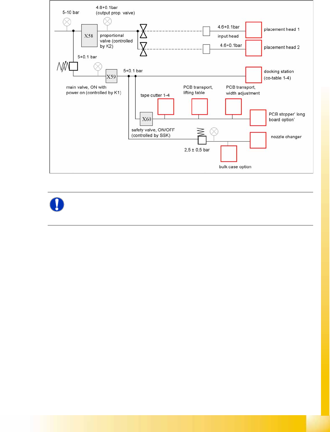
The compressed air with 5-10 bar passes through the filter and is split into 2 main paths. 1st path is into
the main regulator and 2nd. path is into the proportional valve.
path 1: proportional valve X58 for regulating 5.0 +0.1 bar output (automatically adjusted)
C&P (input vacuum generator head 4.6 +0.1)
Twin head segment 1 (input vacuum generator head 4.6 +0.1))
Twin head segment 2 (input vacuum generator head 4.6 +0.1))
path 2: Main valve X59 for regulating 5 +0.1 bar (manually adjusted)
Docking unit for changeover table
Conveyor (width adjustment and lifting table)
Regulator for manually adjusting the air pressure used for bulkcase and nozzle changer, reduced to
2.5 +-0.5 bar
Safety valve X60 for tape cutter and conveyor
Energy and Compressed Air Supply
Switch On Sequence Pneumatic Units Pneumatic System
Student Guide (FSE) SIPLACE X Series and X4I
Edition 01/2009 EN Energy and Compressed Air Supply
199
5.3.3 Switch On Sequence Pneumatic Units
5-26: Switch on sequence for pneumatic units
NOTE:
Prop. valve X58, controlled by relay K2, is immediately powered with machine ON. After
performing the reference run, the valve can be switched off via the software (default setting:
2 minutes).