00196044-05 - sg x und x4i fse_en.pdf - 第208页
Energy and Compressed Air Supply Room for Your Sketches and Notes Cooling the Y Axis Motors for Placement Area 1/2 S tudent Guide (FSE) SI PL ACE X Series and X4I Energy and Compres sed Air Supply Edition 01/20 09 EN 208

Energy and Compressed Air Supply
Cooling the Y Axis Motors for Placement Area 1/2 Room for Your Sketches and Notes
Student Guide (FSE) SIPLACE X Series and X4I
Edition 01/2009 EN Energy and Compressed Air Supply
207
5.4 Room for Your Sketches and Notes

Energy and Compressed Air Supply
Room for Your Sketches and Notes Cooling the Y Axis Motors for Placement Area 1/2
Student Guide (FSE) SIPLACE X Series and X4I
Energy and Compressed Air Supply Edition 01/2009 EN
208
Gantry
Overview
Student Guide (FSE) SIPLACE X Series and X4I
Edition 01/2009 EN Gantry
209
6Gantry
6.1 Overview
The gantries of the SIPLACE X machines consist of one X and one Y axis. Both axes are driven by a
linear motor which is equipped with an integrated temperature sensor. These temperature sensors only
monitor the motor coils. Viewed from the direction of transport, the Y motors move from the right to the
left, in a more positive direction (new coordinate system) and the X motors move from the input conveyor
to the output conveyor, in a more positive direction. The coordinate origin is exactly in the center of the
machine. The placement heads are mounted on the head plates of the respective X axis.
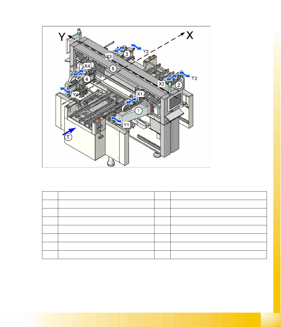
6-1: Position of the gantries in the X4I machine
Legend
X X axis – positive direction of travel Y Y axis – positive direction of travel
1 Gantry 1 in placement area 1 3 Gantry 3 in placement area 2
X1 X axis, gantry 1 X3 X axis, gantry 3
Y3 Y axis, gantry 1 G3 Y axis, gantry 3
2 Gantry 2 in placement area 2 4 Gantry 4 in placement area 1
X2 X axis, gantry 2 X4 X axis, gantry 4
Y2 Y axis, gantry 2 Y4 Y axis, gantry 4
T Transport direction 5 Coordinate origin