00196044-05 - sg x und x4i fse_en.pdf - 第213页
Gantry Travel Ranges and Speed Monitoring Settings S tudent Guide (FSE) SIPL ACE X Series and X4I Edition 01/2009 EN Gantry 213 6.3 Settings 6.3.1 T ravel Rang es a nd Speed Monitoring The travel range of the X and Y axe…
Gantry
Gantry Reference Run (with A364) Searching for the X and Y Commutation Position (A364)
Student Guide (FSE) SIPLACE X Series and X4I
Gantry Edition 01/2009 EN
212
6.2.2 Searching for the X and Y Commutation Position (A364)
A commutation position search for the 3 phases AC-drives on the gantry starts right after the head axes
reference run is succesfully finished.
1. Commutation position search during initial reference run:
Preconditions and function:
Axis reference run must be successfully completed at the relevant placement heads.
2 motor phases are switched to the power supply of the servo amplifier.
The 3-phase AC motor moves to the next suitable magnetic position.
2 other motor phases are switched to the servo power supply and the axis moves further.
These switching steps are repeated multiple times.
The axis reference run is continued with a reference position search for the position measuring system.
6.2.3 Reference Run at X and Y Axis (A364)
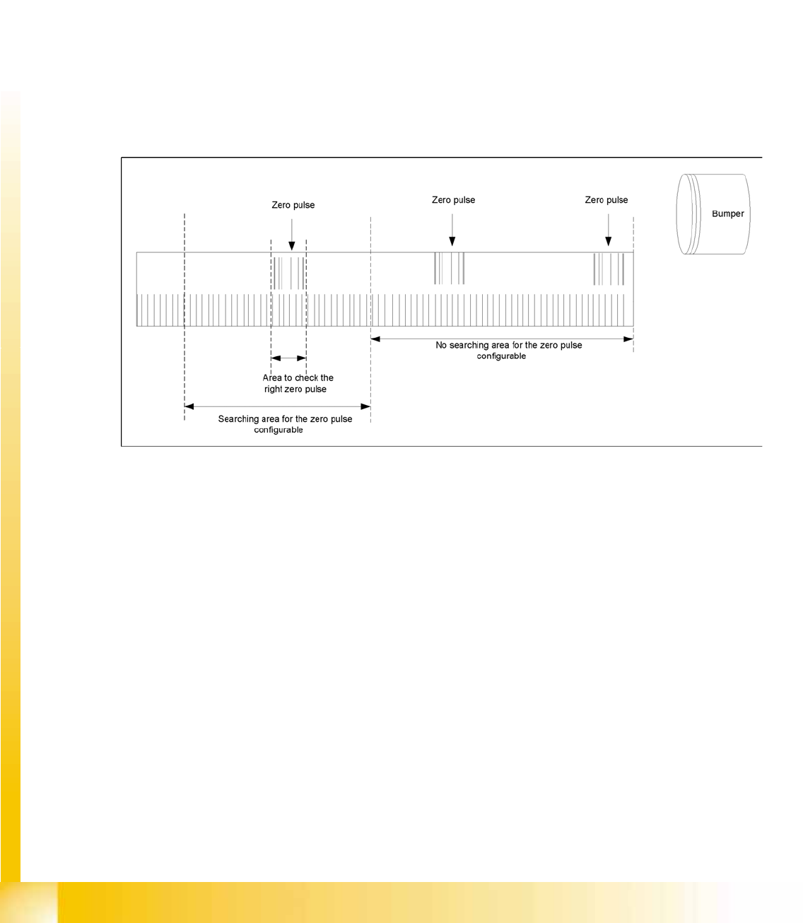
6-4: Zero pulse
Description of zero pulse search:
Requirements:
– The commutation point search has been completed.
– The motor is in position control.
1. After the hardware end stop has been reached and the axis has moved in the opposite direction, the
search for a zero pulse is prohibited within a certain distance of the bumper (approx. 25 mm).
2. After moving out of this prohibited area, the search begins. If the zero pulse is found in this area,
further pulses will be searched for in an area of approx. 2.5 mm If only one zero pulse is found, an
end position message is issued and the reference run is completed.
In the event of a fault, multiple zero pulses or no zero pulses may occur in the defined area. In this
case, the axis will stop and an error message with be issued.
3. The axes are now in a defined position. After finding and checking the zero pulse, the zero point
correction is loaded.
4. The reference run for the main axes has now been completed. The vacuum and height reference
runs will begin.
Gantry
Travel Ranges and Speed Monitoring Settings
Student Guide (FSE) SIPLACE X Series and X4I
Edition 01/2009 EN Gantry
213
6.3 Settings
6.3.1 Travel Ranges and Speed Monitoring
The travel range of the X and Y axes will be determined during machine calibration.
This means that, during travel range calibration, the axis concerned moves as far as possible towards
the minimum or maximum position, until the set axis card target value is no longer reached. It is then
assumed that the hardware end position switch (bumper) has been reached. In a time window of approx.
10 ms, the greatest actual value achieved is taken to calculate the travel range.
To guarantee an appropriate safety gap before the hardware end switch is touched, a certain distance
is deducted from the set travel range. This enables the axis to brake in time, even when errors occur.
The X axis moves to the left and right bumper and measures their positions with a safety distance of 2.0
mm. The SW also deducts a value of 0.5 mm from the maximum or minimum travel range.
The Y axis only moves to its minimum position (gantry 1/2) or to its maximum position (gantry 3/4).
The position opposite is then calculated.
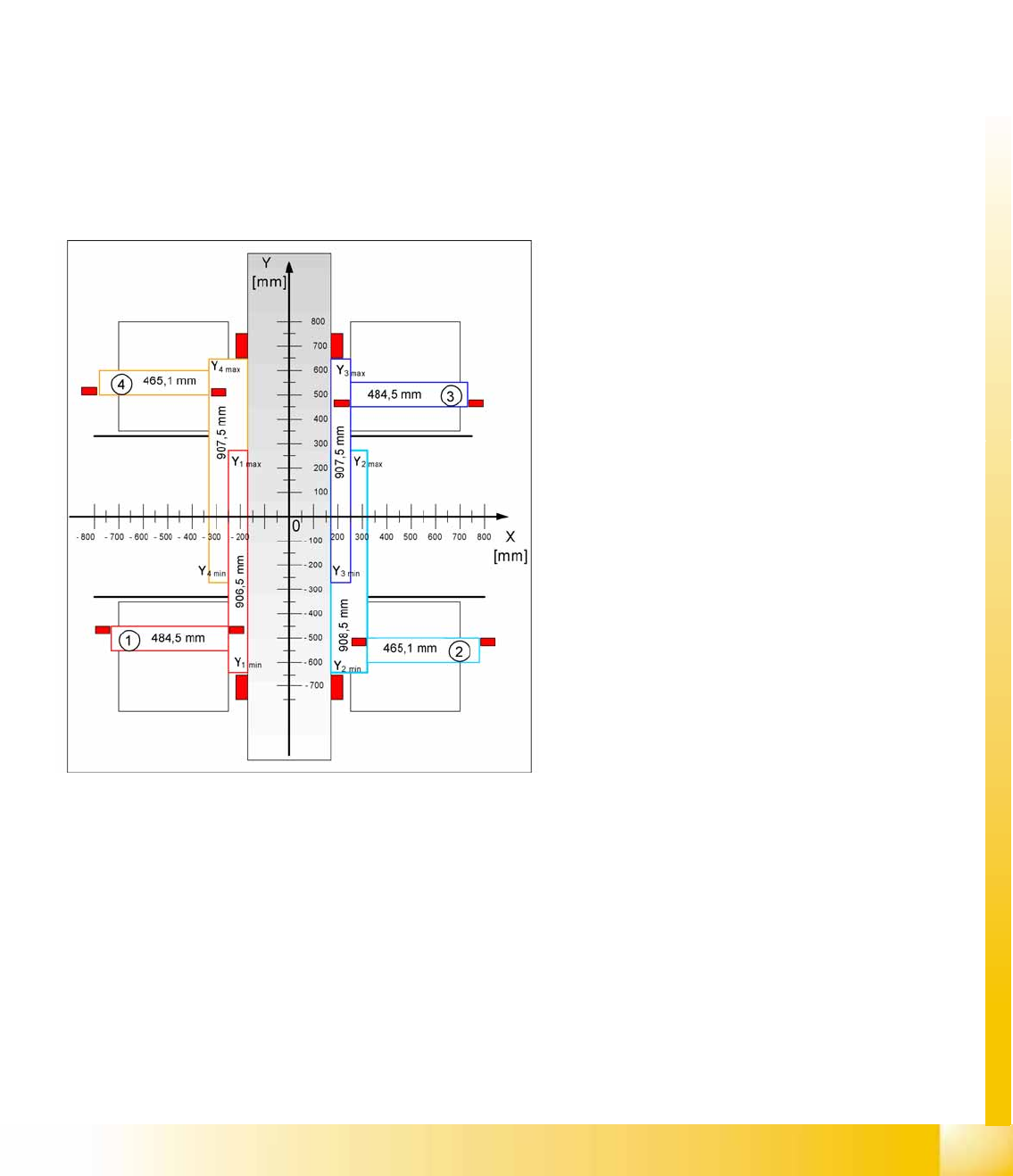
6-5: Travel ranges for X and Y axes (X4I)
Legend
1 - 4 = gantry 1 to 4
The end of the X axis travel range is + or -
0.5 mm before the software limit switch, which is
1.5 mm before the bumper. A safety distance of
2.0 mm to the bumper is adequate, if the X axis
moves into this area with excessive speed.
The end of the Y axis travel range is + or -
2.0 mm before the software limit switch. The Y
axis travel range for a particular placement area is
monitored in one direction by the software limit
switch and a bumper. In the other direction, there
is a permanent exchange of communication
between the axes and their positions, via the SPI
Bus (see description of the anticrash function).
Gantry
Settings PCB Boards on the Gantry
Student Guide (FSE) SIPLACE X Series and X4I
Gantry Edition 01/2009 EN
214
6.3.2 PCB Boards on the Gantry
The printed circuit boards which are described in this chapter are basically identical on each gantry and
do not depend on the head configuration. The gantry identification settings and the CAN bus terminating
resistance settings are defined at the DIP switch on the head interface.
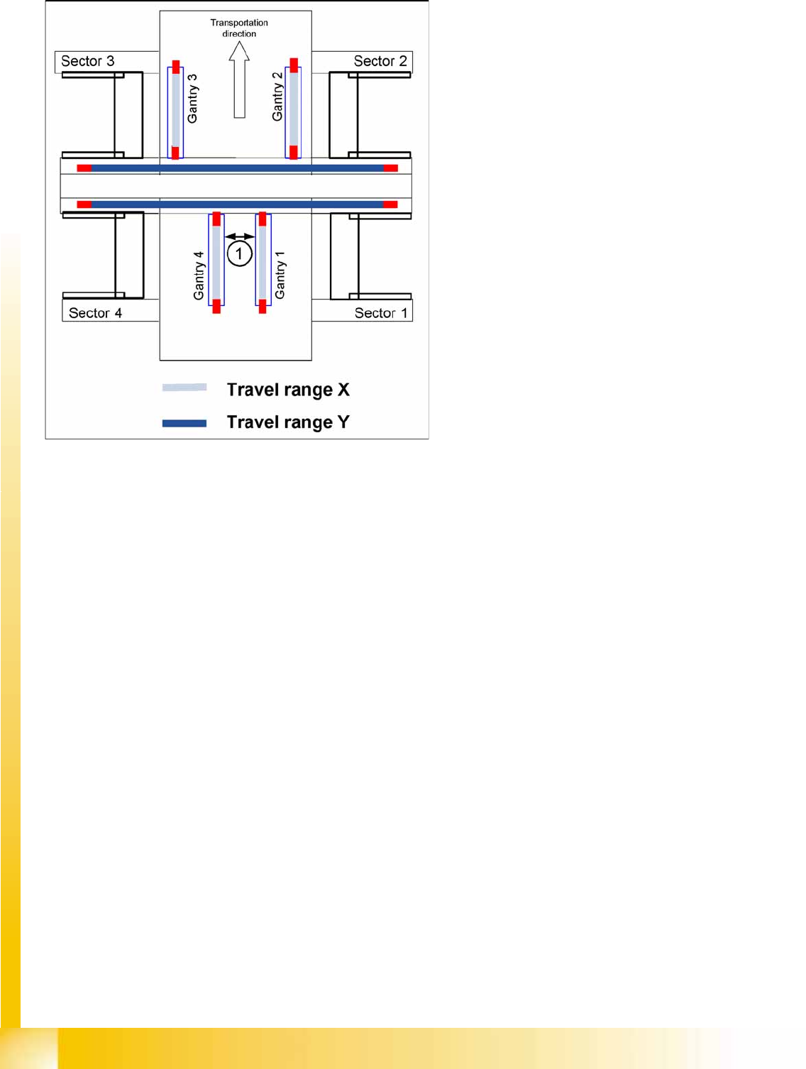
6-6: Travel ranges for X and Y axes
Legend
1. The minimum safety distance between the
gantries, during placement: minimum 4 mm.
Depending on the placement mode (i-placement
or alternating), the gantries will operate in one
placement area fully independently. This means
that one gantry does not need to know the position
of the other one.