00196044-05 - sg x und x4i fse_en.pdf - 第218页
Gantry Settings PCB Boards on the Gantry S tudent Guide (FSE) SI PL ACE X Series and X4I Gantry Edition 01/2009 EN 218 6.3.2.3 CAN Processor Board 16 Bit The 16 bit CAN processors are used fo r various func tions on the …
Gantry
PCB Boards on the Gantry Settings
Student Guide (FSE) SIPLACE X Series and X4I
Edition 01/2009 EN Gantry
217
DIP Switches on the Head Interface
* Not all gantries may be available, depending on the machine type.
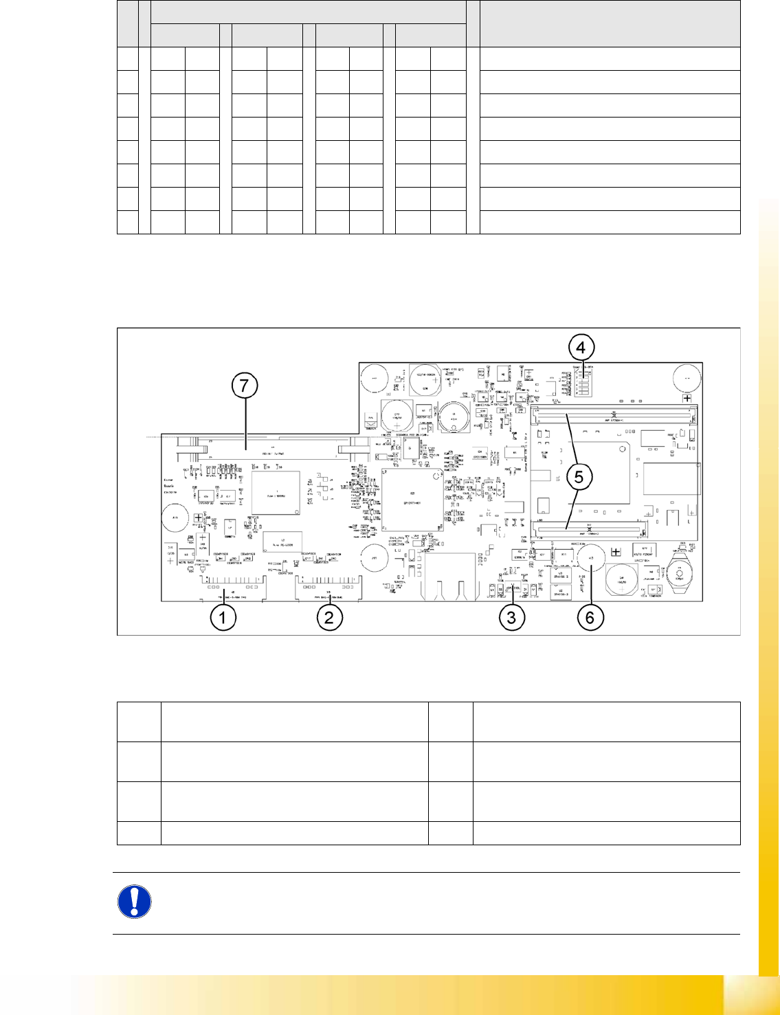
6.3.2.2 Vision Board (Digital Version 02)
The Vision processor board is fixed to the head interface of each gantry.
6-9: Vision board
Legend
S Setting for gantry* Comments
1 2 3 4
1 OFF ON OFF ON P0 – gantry ID0 address switch 1 --> gantry
2OFF OFF ON ONP1 – gantry ID1 address switch 2 --> gantry)
3XX XX XX XXOFF: Twin Head – ON: C&P head
4 OFF OFF OFF OFF Boot
5 OFF OFF OFF OFF Reset – CAN processor, 16 bit (TQM module)
6 OFF OFF OFF OFF CAN_ID0
7 OFF OFF OFF OFF CAN_ID1
8 OFF OFF OFF OFF WP_EEPROM
1 X8 Connector illumination and video signals
PCB camera
5 CAN processor 16 Bit (TQM module)
2 X3 Connector illumination and video signals
component camera
6 DC/DC converter 15 --> 5V for Vision system.
3 LED‘s P15V - 15Volt / Vcc - Power supply Vision
board
7 Connector X4 – connection for video signals to
trailing cable
4 DIP switch
NOTE:
The DIP switch configuration for the gantry configuration is described in Section (6.3.2.4 Check
the DIP Switches
J
219 ) .
Gantry
Settings PCB Boards on the Gantry
Student Guide (FSE) SIPLACE X Series and X4I
Gantry Edition 01/2009 EN
218
6.3.2.3 CAN Processor Board 16 Bit
The 16 bit CAN processors are used for various functions on the following assemblies: (see also chapter
Communication and Control)
Vision board: communication and control via CAN bus to station computer.
Head processor board (C500), if a C&P head has been configured: control of head processes and
of vacuum generators
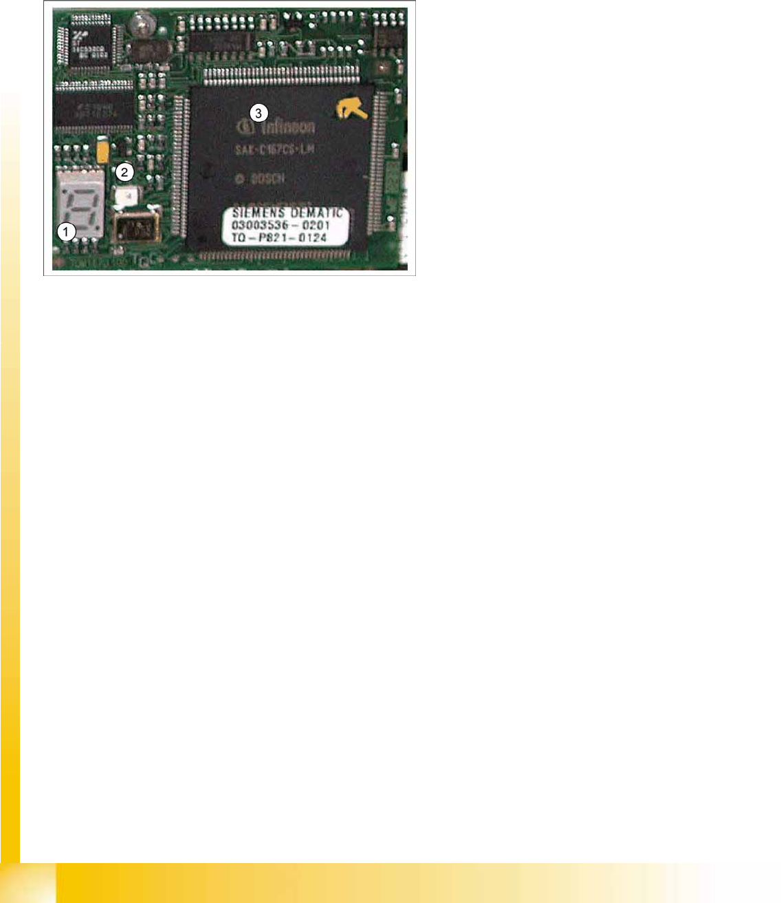
Description of 7 segment display (in normal mode the dot is flashing "."):
After switching on, a "0" appears on the display
Display "b" --> BIOS starts.
Display flashes alternatively between "b" and "." --> no application available or unable to start
application.
Display "-I" and "I-" --> application has been loaded and will now start.
The dot "." on the display is flashing. --> the processor has booted and is ready for operation.
6-10: 16 bit processor (TQM module)
Legend
1. 7 segment display
2. LED
The LED is red if you perform a manual
RESET of the processor.
3. 16 bit processor
Gantry
PCB Boards on the Gantry Settings
Student Guide (FSE) SIPLACE X Series and X4I
Edition 01/2009 EN Gantry
219
6.3.2.4 Check the DIP Switches
DIP Switches on the Head Interface
* Not all gantries may be available, depending on the machine type.
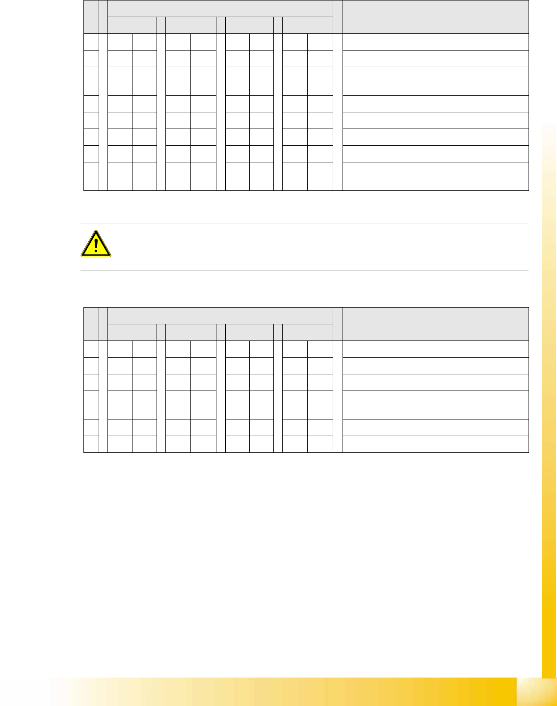
DIP Switch on the Vision Board (Digital Version 02)
* Not all gantries may be available, depending on the machine type.
S Gantry* Comments
1 2 3 4
1 OFF ON OFF ON P0 - Gantry address switch 1
2OFF OFF ON ONP1 - Gantry address switch 2
3ONONONONCAN R - CAN terminator (always OFF for Twin
Head)
4 OFF OFF OFF OFF Boot - CAN processor 16 bit
5 OFF OFF OFF OFF Reset - CAN processor 16 bit
6 OFF OFF OFF OFF C0 - CAN Address switch
7 OFF OFF OFF OFF C1 - CAN Address switch
8 OFF OFF OFF OFF WPE - Write protect enable at the moment
OFF
ATTENTION:
Switch 3 (does not apply for X4I machines)
With Head Modularity pay attention: That terminating CAN resistor is set correctly. This means,
Switch 3 is set to ON for C&P and to OFF for Twin Head.
S Gantry* Comments
1 2 3 4
1 OFF OFF OFF OFF Reset - CAN processor
2 OFF ON OFF ON PID0 address switch 1 -> gantry
3OFF OFF ON ONPID1 address switch 2 -> gantry
4 OFF OFF OFF OFF CAN R - switch for the terminal resistor on the
CAN bus
5ONONONONSpeed: ON = 1 Mbit/s, OFF = 500 Kbit/s
6ONONONONCAN ID - for X machine ON