00196044-05 - sg x und x4i fse_en.pdf - 第225页
Gantry Checking the Zero Pulse Signal Track Signals and Zero Pulse S tudent Guide (FSE) SIPL ACE X Series and X4I Edition 01/2009 EN Gantry 225 X10 on Y Axis Gantry Interface X24 on X Axis Head Interface Connector assign…
Gantry
Track Signals and Zero Pulse Checking the Zero Pulse Signal
Student Guide (FSE) SIPLACE X Series and X4I
Gantry Edition 01/2009 EN
224
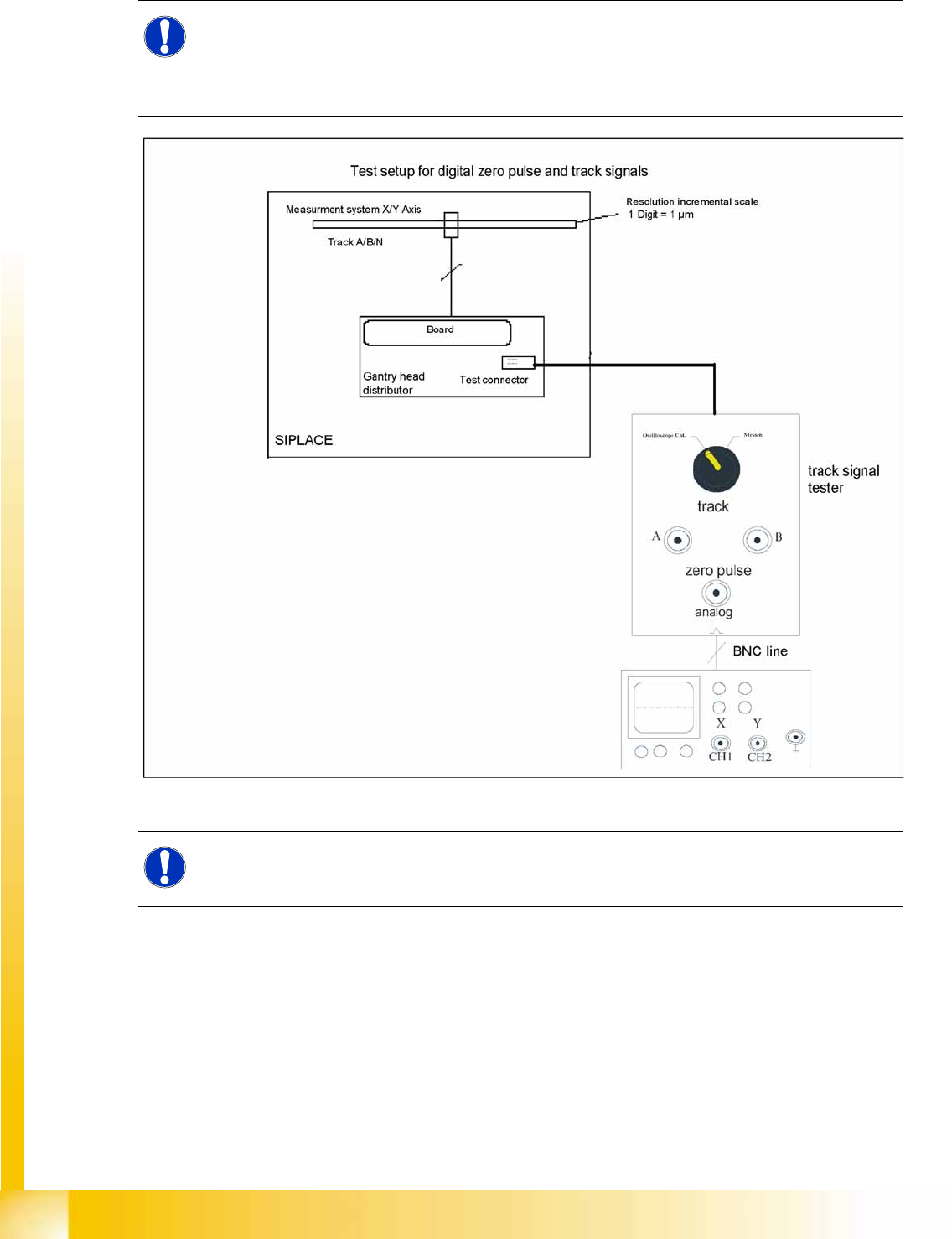
6.4.1.2 Measuring the Digital Zero Pulse Signal
6-16: Measurement procedure for checking the digital zero pulse signal and the digital track signals.
NOTE:
You can also use the BNC socket on the axis test box to check the zero pulse signal (inverted
display of zero pulse signal). The digital signals can be checked (for error location) at connectors
X10 and X24 of the gantry and at the head interface (calculate extra time for Y axes,
dismounting the covers).
NOTE:
The procedure for measuring the digital zero pulse is identical to that for measuring the analog
zero pulse.
Gantry
Checking the Zero Pulse Signal Track Signals and Zero Pulse
Student Guide (FSE) SIPLACE X Series and X4I
Edition 01/2009 EN Gantry
225
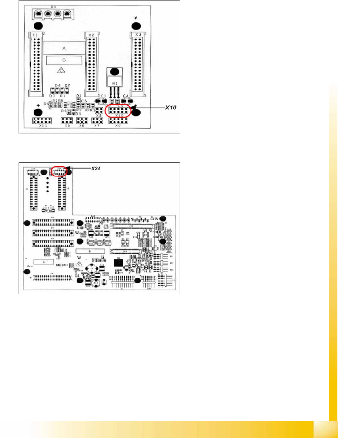
X10 on Y Axis Gantry Interface
X24 on X Axis Head Interface
Connector assignment X10:
1. Pin 1 Ground
2. Pin 2 Track A
3. Pin 3 Track A\
(A\ means inverted A)
4. Pin 4 Ground
5. Pin 5 Track B
6. Pin 6 Track B\
7. Pin 7 +5V
8. Pin 8 Track N
9. Pin 9 Track N\
10. Pin 10 Key
Connector assignment X24:
1. Pin 1 Ground
2. Pin 2 Track A
3. Pin 3 Track A\
4. Pin 4 Ground
5. Pin 5 Track B
6. Pin 6 Track B\
7. Pin 7 +5V
8. Pin 8 Track N
9. Pin 9 Track N\
10. Pin 10 Key
Gantry
Track Signals and Zero Pulse Checking the Track Signals
Student Guide (FSE) SIPLACE X Series and X4I
Gantry Edition 01/2009 EN
226
6.4.2 Checking the Track Signals
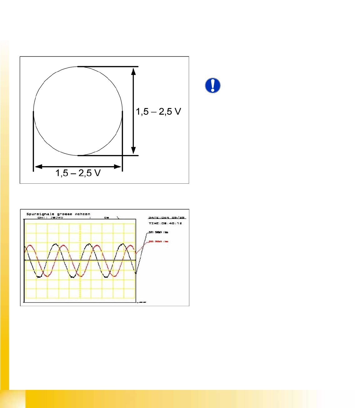
6.4.2.1 Analog Track Signals
To check the track signals, connect the track signal tester and the oscilloscope. (see Section (6.4.1.1
Measuring the Analog Zero Pulse Signal
J
222 ) )
X Switch the machine on.
X Switch the track signal tester to
Calibrate oscilloscope.
X Switch the oscilloscope to
DC, Refr., Non Store, Auto (20 ms).
X Voltages V/Division decrease up to 0.5 V/Div.
X Switch the oscilloscope to
X/Y
--> Illuminated point will appear!
X Move the point into the middle of the display.
X Measurement system to position
Sinus amplifier output.
X Manually move the selected axis back and forth.
6-17: Analog track signals A and B in X/Y oscilloscope mode
X The adjacent picture should appear on the
oscilloscope.
NOTE:
A new version of the incremental
encoder (one field lens) can recognize
signals from 1.8 to 3.6 Vss.
6-18: Analog track signals 90° phase shift
X Switch the oscilloscope to normal operation.
X The adjacent picture should appear on the
oscilloscope.