00196044-05 - sg x und x4i fse_en.pdf - 第231页
Gantry Checking the X Axis Dynamics Axis Control S tudent Guide (FSE) SIPL ACE X Series and X4I Edition 01/2009 EN Gantry 231 6.5.2.3 T ravel Time T able for C&P20A X Axis 6.5.2.4 T ravel Time T able for CPP X Axis 6…
Gantry
Axis Control Checking the X Axis Dynamics
Student Guide (FSE) SIPLACE X Series and X4I
Gantry Edition 01/2009 EN
230
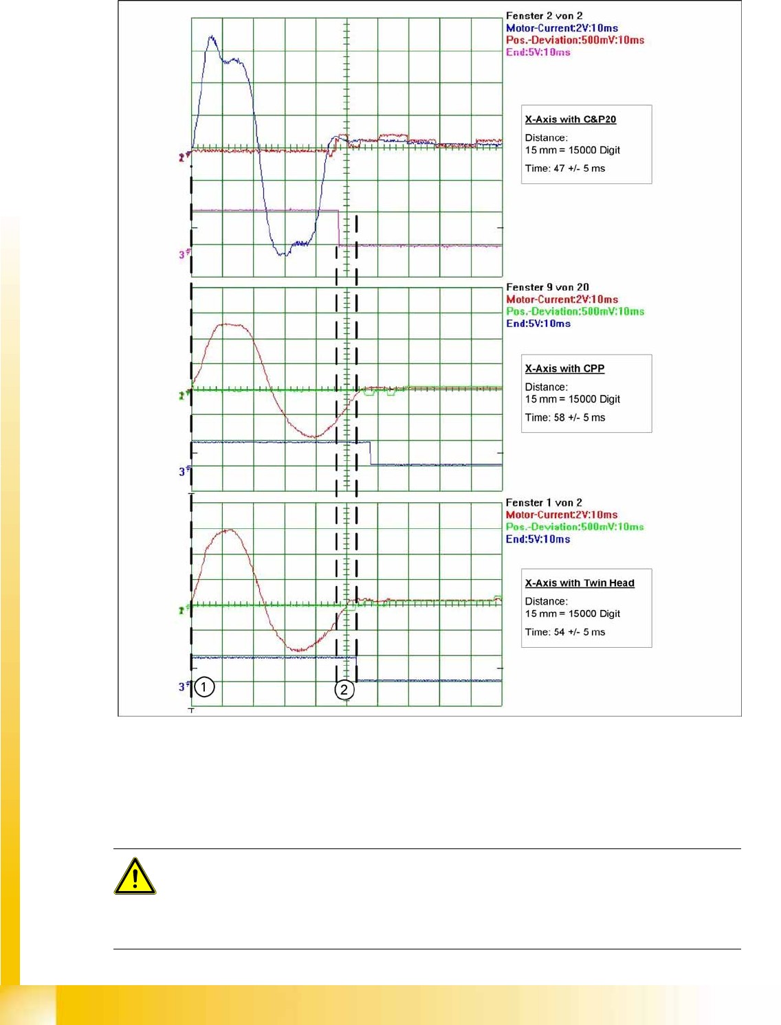
6.5.2.2 Comparison of X Axis Travel Profile for C&P20A, CPP and Twin Heads
6-22: Signal path at 15000 digit travel range of X axis for different head configurations
Legend
1. Axis start
2. The end position signal is triggered at different times, depending on the axis records for the 3 head
configurations.
ATTENTION:
The maximum position deviation for placement with:
C&P20A: 12 µm (digits)
CPP: 10 µm (digits)
Twin Head: 5 µm (digits)

Gantry
Checking the X Axis Dynamics Axis Control
Student Guide (FSE) SIPLACE X Series and X4I
Edition 01/2009 EN Gantry
231
6.5.2.3 Travel Time Table for C&P20A X Axis
6.5.2.4 Travel Time Table for CPP X Axis
6.5.2.5 Travel Time Table for Twin Head X Axis
Distance / digit X gantry axis with C&P20A
Target time / ms Tolerance /ms
600 27 +/-5
1000 27 +/-5
2000 27 +/-5
5000 27 +/-5
15000 42 +/-5
20000 48 +/-5
50000 74 +/-5
100000 103 +/-5
200000 146 +/-5
Distance / digit X gantry axis with CPP
Target time / ms Tolerance /ms
600 27 +/- 5
1000 27 +/- 5
2000 27 +/- 5
5000 30 +/- 5
15000 43 +/- 5
20000 49 +/- 5
50000 76 +/- 5
100000 107 +/- 5
200000 151 +/- 5
Distance / digit X gantry axis with Twin Head
Target time / ms Tolerance /ms
600 26 +/- 5
1000 28 +/- 5
2000 34 +/- 5
5000 41 +/- 5
15000 54 +/- 5
20000 59 +/- 5
50000 87 +/- 10
100000 125 +/- 10
200000 170 +/- 10
300000 209 +/- 15
Gantry
Axis Control Checking the Y Axis Dynamics
Student Guide (FSE) SIPLACE X Series and X4I
Gantry Edition 01/2009 EN
232
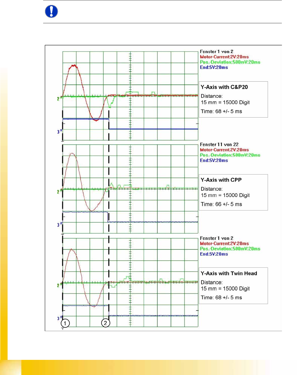
6.5.3 Checking the Y Axis Dynamics
6.5.3.1 Measurement Setup
6.5.3.2 Comparison of Y Axis Travel Profile for C&P20A, CPP and Twin Heads
6-23: Signal path at 15000 digit travel range of Y axis for the different head configurations
NOTE:
The measurement procedure follows the same preparations and procedures as for the X axis.