00196044-05 - sg x und x4i fse_en.pdf - 第238页
C&P20A Overview C&P20A Technical Data S tudent Guide (FSE) SI PL ACE X Series and X4I C&P20A Edition 01/2009 EN 238 7.2.1 C&P20A T echnical Dat a 7.2.2 C&P20A Function C&P20A principle Like the …
C&P20A
C&P20 And C&P20A Heads
Student Guide (FSE) SIPLACE X Series and X4I
Edition 01/2009 EN C&P20A
237
7 C&P20A
7.1 C&P20 And C&P20A Heads
7.2 Overview
NOTE:
Older X machines use C&P20 heads. These are not supported by SW70x.
Machines with SW >= 701 only support C&P20A heads. These are marked with a label on the
head.
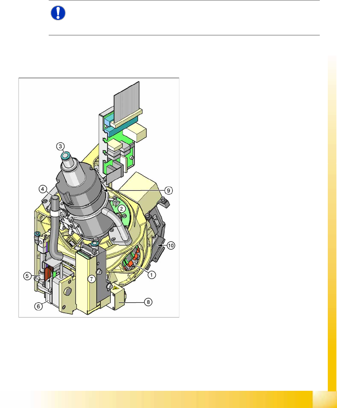
7-1: Overview of Collect&Place20A head
Legend
1. Star with 20 segments (DP drives)
2. Board for "hold circuit vacuum sensor"
3. Compressed air supply for holding, pickup and
place circuits
4. Cooling for X linear motor (discharged air from
pressure control valve)
5. Z axis return cylinder
6. Z linear motor with measuring system
7. Pressure control valve for pickup and place
circuit
8. Component sensor
9. Star motor with incremental encoder
10. Component Camera
C&P20A
Overview C&P20A Technical Data
Student Guide (FSE) SIPLACE X Series and X4I
C&P20A Edition 01/2009 EN
238
7.2.1 C&P20A Technical Data
7.2.2 C&P20A Function
C&P20A principle
Like the C&P12, the C&P20A works according to the Collect&Place principle.
While the Star revolves, the components can be rotated into the required centering position. After
optical measurement, the components are again rotated into the correct placement positions and
placed, while the star is revolving.
This means that each segment is equipped with its own DP drive, to allow angle adjustment while
the star is revolving. Each DP drive has its own control board and vacuum generator.
The communication with the 20 DP drives is via the head CAN bus with the help of a contactless E/
D transformer. This makes continuous star rotation possible.
In the pickup and placement position, the Z axis moves the complete DP drive unit upwards or
downwards.
Compressed air is supplied to the 20 Venturi nozzles in the holding circuit via the hollow designed
shaft of the Star motor.
A pressure control valve in the pickup/placement circuit is used to increase the vacuum during pickup
and apply air blast to eliminate the holding circuit vacuum and release the component, during
placement.
In the pickup/placement position, the standard component sensor is used to check the presence of
components on the nozzle, both before and after pickup/placement.
NOTE: Head Modularity
The axis dynamic settings at head replacement are adjusted automatically by axis parameter
changes during the reconfiguration.
Description C&P20A
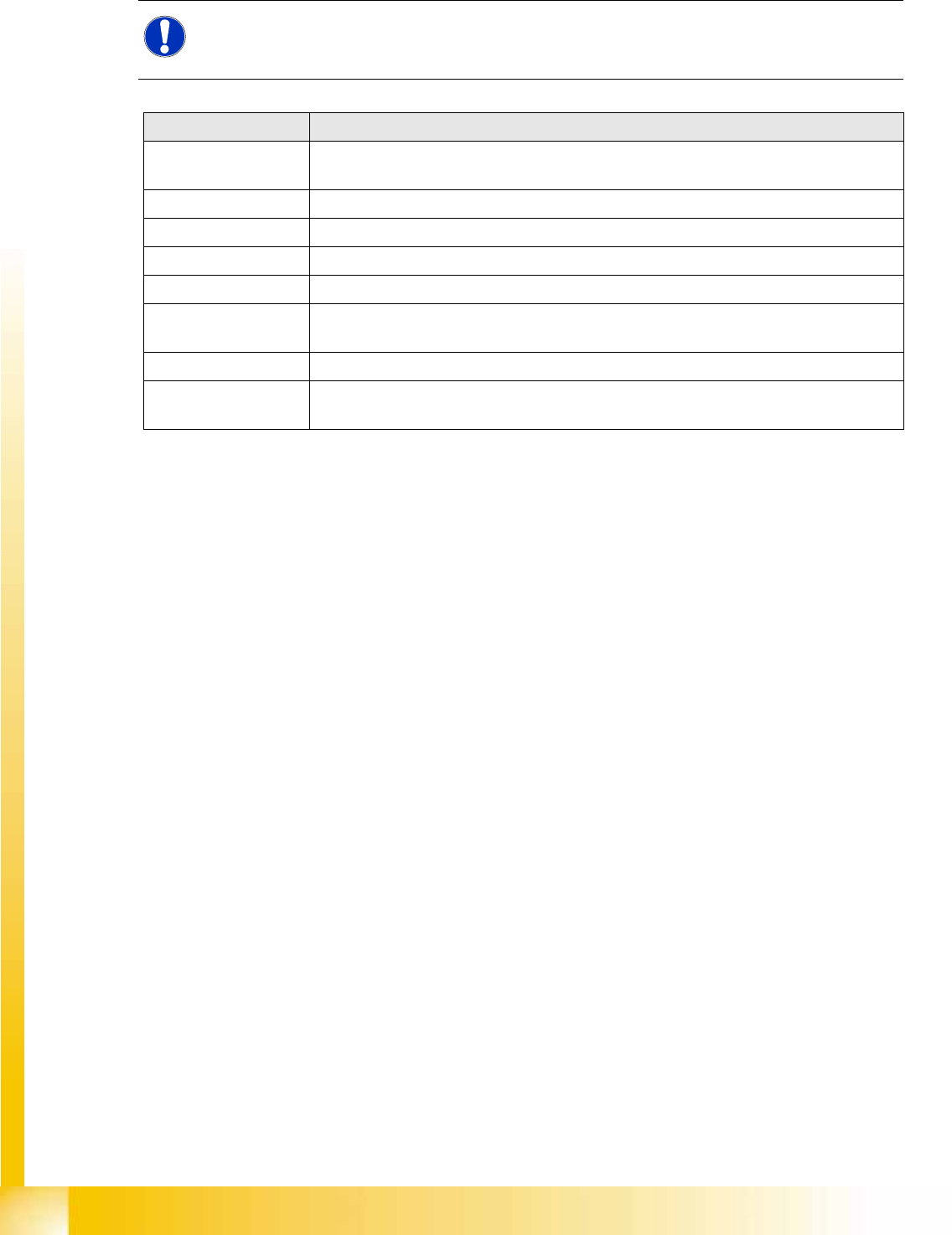
Component size 01005 to 2220, Melfs, Bare Dies, Flip Chips, SOT, SOD, components up to max.
6x6mm
Component height 4.0 mm
Component weight max. 1g
Placement accuracy +/-55µm at 4 (sigma)
Angle accuracy +/-0.8° at 4 (sigma)
Placement force 2.0 N +/-0.5 N
3.5 N and 4.5 N +/-1 N
Nozzle types 1001, 1003-1007, 1011, 1032-1037, whereby 1235 is for the calibration tool
Nozzle changer set up for each 6 magazine with 12 garage,
X4I: 4 magazines each at locations 2/4
C&P20A
Parts Overview with Function Description Overview
Student Guide (FSE) SIPLACE X Series and X4I
Edition 01/2009 EN C&P20A
239
Advantages compared with DLM heads
The holding circuit has one venturi nozzle for each segment: No more interference between the
segments.
No vacuum plunger: Digital pressure control valve: Faster switching times between vacuum and air
blast.
The placement star is now positioned at an angle this lead to a compact space for arranging the 20
segments and integrating the component camera into the head.
Lower inlet pressure: Lower air consumption per segment.
Autonomous rotation and positioning of each segment: Increases placement performance.
No swiveling in and out of DP station onto the segment: Greater accuracy and robustness.
Component sensor in the pickup/placement position: Greater placement reliability.
Digital camera interface: Faster image evaluation
Linear motor with Z drive : reduction of moving mass this increases placement capacity.
7.2.3 Parts Overview with Function Description
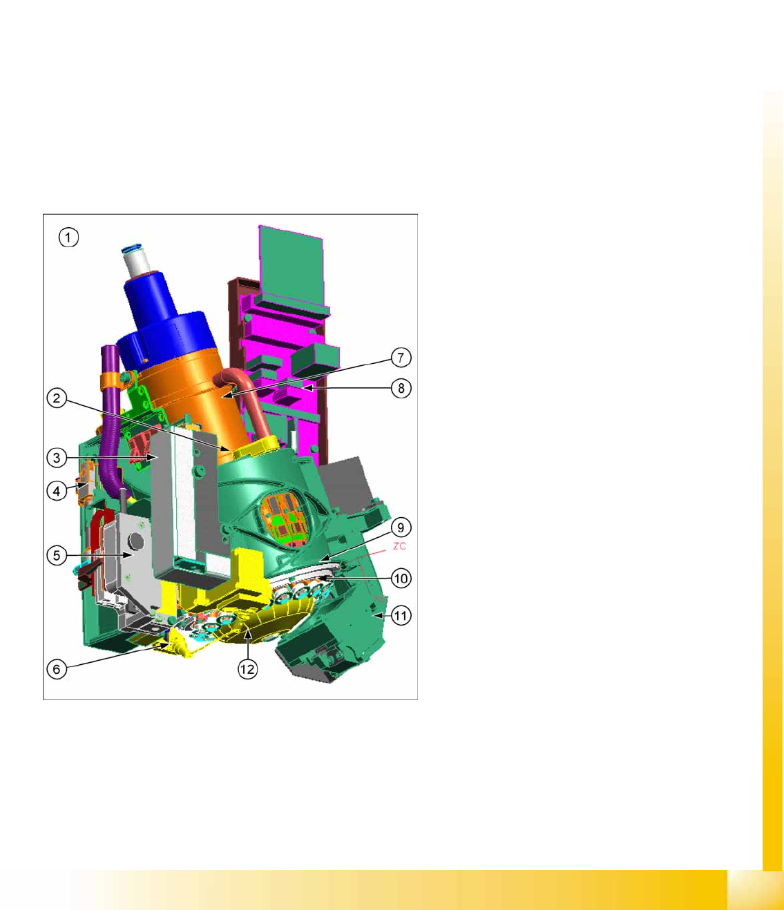
7-2: C&P20A parts
This chapter describes the main parts of the
C&P20A head and their technical function.
The description is ordered according to the
sequence of disassembly for servicing.
Legend
1. C&P20A assembly
2. E/D transformer
3. Vacuum generator (Placement/Pick up circuit)
4. Pneumatic return unit
5. Z drive
6. Component sensor
7. Star motor
8. Intermediate distributor board
9. Raceway
10. DP drive
11. Component Camera
12. Silencer holding circuit