00196044-05 - sg x und x4i fse_en.pdf - 第241页
C&P20A Parts Overview with Function Descr iption Overview S tudent Guide (FSE) SIPL ACE X Series and X4I Edition 01/2009 EN C&P20A 241 7.2.3.2 Z axis Z Drive Function Legend 1. Incremental measurem ent system, re…
C&P20A
Overview Parts Overview with Function Description
Student Guide (FSE) SIPLACE X Series and X4I
C&P20A Edition 01/2009 EN
240
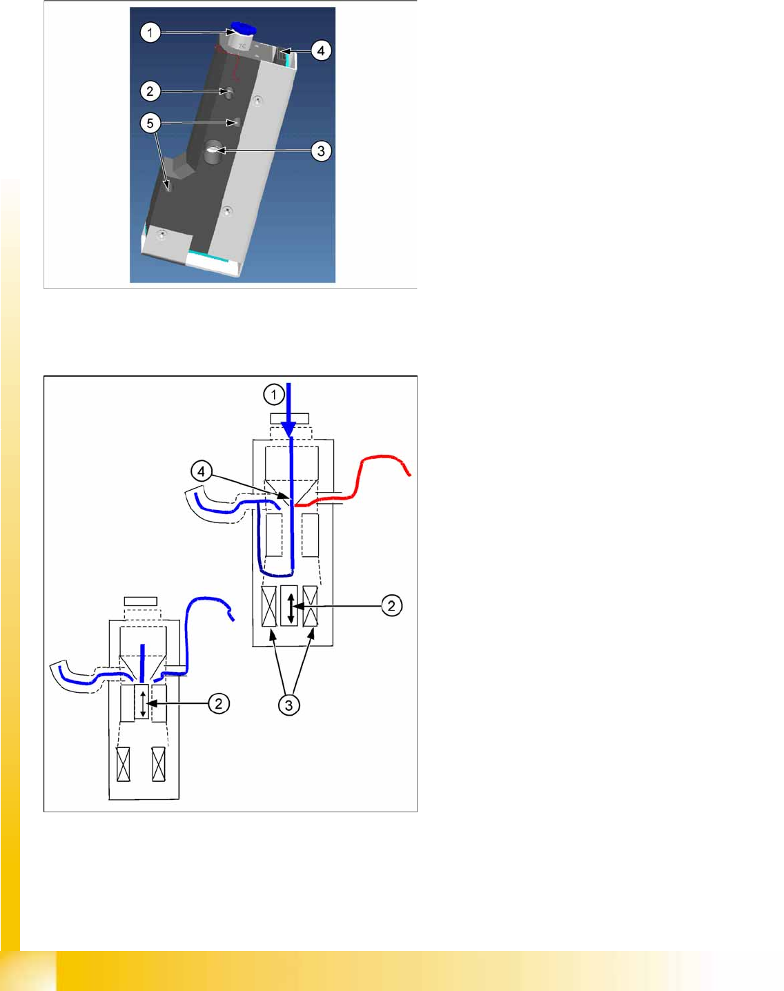
7.2.3.1 Pressure Control Valve
C&P20A function units
Pressure Control Valve - Function
Pressure control valve (digital)
The pressure control valve supplies the
pickup/placement circuit with vacuum during
the pickup process and switches over to air
blast during placement.
This valve is fixed to the placement head with
two screws and can be replaced during
service work.
Legend
1. Compressed air connection
2. Vacuum/air blast for pickup/placement circuit
3. Discharged air, for cooling the X linear motor
4. Energy and data supply
5. Pressure control valve fixture
Legend
1. Compressed air
2. Pistons
3. Motor
4. Venturi nozzle
After initialization, the piston is in a central
position, in which neither vacuum nor air blast
is applied to the nozzle.
During pickup, the piston is always in the open
position, in which maximum vacuum is
produced and applied to the nozzle.
The function
Early vacuum
should always be
switched on for the C&P20A head. However, if
this function is switched off, the piston will be
in the "open position". The vacuum will only be
switched on again after the "light barrier down"
signal has been issued . -> 2 additional
switching steps -> time loss.
C&P20A
Parts Overview with Function Description Overview
Student Guide (FSE) SIPLACE X Series and X4I
Edition 01/2009 EN C&P20A
241
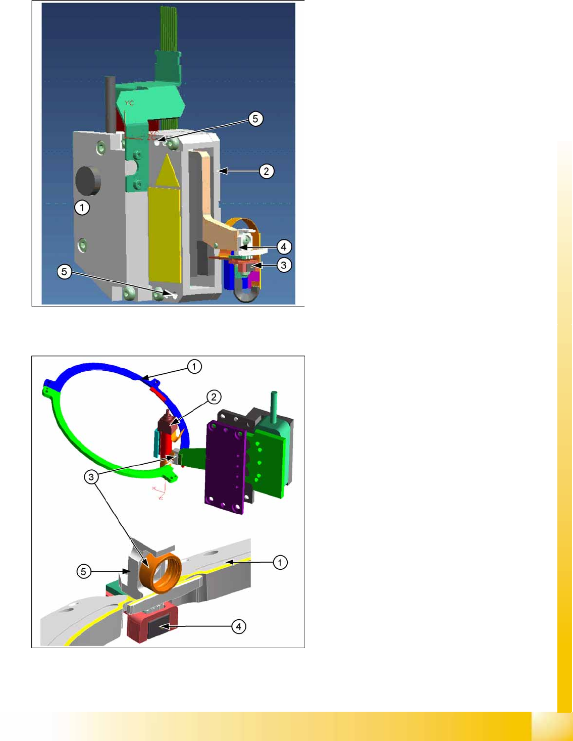
7.2.3.2 Z axis
Z Drive Function
Legend
1. Incremental measurement system, resolution
0.5 µm
2. Linear motor, primary part, moves up and
down between the secondary parts.
3. Light barrier Z-down emits the end position
signal for the Z axis.
4. Snap jaws: The ball bearing for the DP drive is
rotated via the star axis into the jaw, allowing
the segment to be moved upwards and
downwards.
5. Z axis fixtures
The Z axis and return unit are fixed to the head as
a complete unit, with two screws, and can be
easily replaced during service work.
Legend
1. Raceway
2. Segment
3. Ball bearings
4. Light barrier down
5. Snap jaws
The jaws are installed on the primary part of
the Z motor, for mechanical docking of the
segments.
A Z down sensor is located in the placement
position, for recognition of the Z axis put down
position. This recognizes a relative movement
between the nozzle and DP segment. When
the Z axis springs into place, this sensor sends
a signal to the axis controller board. The "light
barrier down" signal is directly linked to the
measurement signal of the Z axis incremental
encoder.
C&P20A
Overview Parts Overview with Function Description
Student Guide (FSE) SIPLACE X Series and X4I
C&P20A Edition 01/2009 EN
242
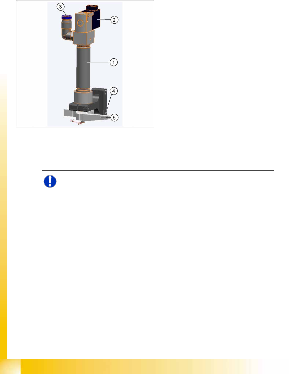
7.2.3.3 Return unit
Return unit functions
At zero current, the bearing friction of the Z axis is not sufficient to protect the axis from falling down. A
pneumatic return system has been installed to protect the Z axis should the gantry be moved when the
machine is switched off. This return unit keeps the Z axis in the safe, upper position during zero current.
7.2.3.4 Component sensor
The component sensor is a standard feature on the C&P20A head and no longer an option as in the DLM
heads. Also, the function and position of the component sensor is different to that for the DLM heads.
The component sensor is in the pickup/place position and the Z axis moves during the upwards and
downwards movement of the laser beam. If the laser beam is interrupted or when it is released again,
the exact Z axis position is read out and the corresponding evaluation started.
(Before Pick up: No Component on the nozzle, After Pick up: Component on the nozzle;
Placement: Component still on the nozzle, After placement: No Component on the nozzle)
Legend
1. Pneumatic cylinder
2. Solenoid valve
3. Compressed air connection
4. Return unit fixtures
5. Z axis driver
The return unit is installed on the Z axis and is
responsible for protecting the Z axis from damage,
by moving it into a safe area in the case of
unexpected events e.g. power cuts or machine
shutdown.
The return unit is fixed with two screws and can be
easily replaced during service work.
NOTE:
The Z axis control system is designed to ensure that, should the machine power supply fail (or
be switched off), there is always enough power temporarily stored by the Z motor servo unit and
axis controller board to move the Z axis to the upper position.
Power failure is recognized by the issuance of a "Power fail" signal. This "Power fail" signal
enables the relevant function (upwards movement and activation of the return unit) on the axis
controller board.