00196044-05 - sg x und x4i fse_en.pdf - 第262页
C&P20A Pickup and Placement Cycle for C&P20A Board Position Recognition S tudent Guide (FSE) SI PL ACE X Series and X4I C&P20A Edition 01/2009 EN 262 7.4.3 Board Position Recognition We differentiate betwee n…
C&P20A
Working Position on Placement Head Pickup and Placement Cycle for C&P20A
Student Guide (FSE) SIPLACE X Series and X4I
Edition 01/2009 EN C&P20A
261
7.4 Pickup and Placement Cycle for C&P20A
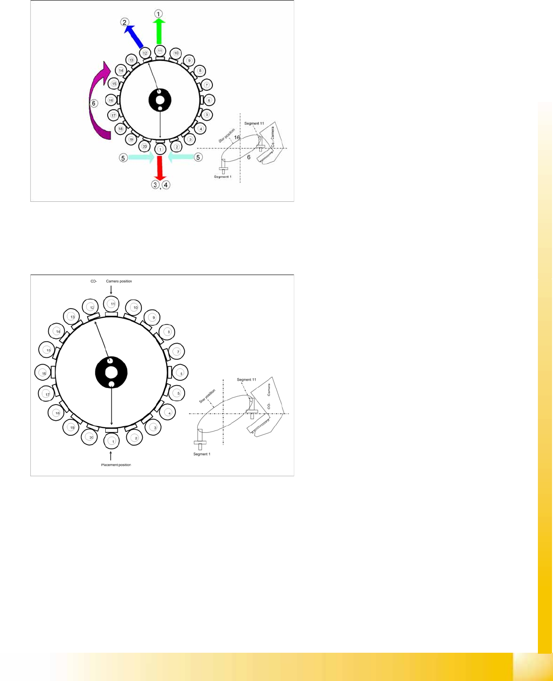
7.4.1 Working Position on Placement Head
7.4.2 C&P20A in Home Position 0°
7-18: Working Position on Placement Head
Legend
1. Optical centering (component camera)
2. Vacuum measurement holding circuit
3. Vacuum measurement placement circuit
4. Pickup/placement station and reject position
5. Position of component sensor
6. Working direction
7-19: C&P20A in Home Position 0°
Star position
Digits: 10
Angle: 0°
1° is equivalent to 1000 digits
The Z axis return unit prevents segment 1 from
falling.
C&P20A
Pickup and Placement Cycle for C&P20A Board Position Recognition
Student Guide (FSE) SIPLACE X Series and X4I
C&P20A Edition 01/2009 EN
262
7.4.3 Board Position Recognition
We differentiate between standard position recognition and dual position recognition.
PCB – position recognition (standard position recognition)
Board position recognition is used to determine the exact position of the board in the machine (conveyor
--> placement area).
PCB position recognition is performed with gantry 4 for placement area 1 and with gantry 2 in placement
area 2.
There should be at least two fiducials on each PCB. These are then used to calculated the X/Y position
and the rotary angle of the board, in the conveyor system.
The fiducials should not be on the same line as one another.
Up to 3 fiducials can be programmed for position recognition. With the third fiducial you can also
determine and correct any displacement within the board (shrinkage, stretched).
Dual position recognition (for alternating mode only)
Dual position recognition is required in order to guarantee the placement accuracy. Materials change
according to the temperature they are subjected to and the same applies to the machine gantries.
Dual position recognition is performed with gantry 1 in placement area 1 and with gantry 3 in placement
area 2.
In the case of dual position recognition, gantry 1/3 uses the fiducial position recognition values from
gantry 2/4 to calculate the placement offset for gantry 1/3. Depending on the arrangement of fiducials on
the board, either 2 or 3 fiducials will be used for dual position recognition.
The fiducials for dual position recognition are selected so that the calculation performed can be as
accurate as possible.
Temperature compensation
A further measure to ensure placement accuracy is the temperature compensation with the help of
sensors on the head plate. The head plate features two temperature sensors, the temperature values of
which are regularly checked via a separate bus system.
The software uses these temperature values to calculate an offset value, which is added to the head
offset.
Head offset SW 60x is the distance PCB <--> component camera
Head offset SW 70x is the distance PCB camera <--> nozzle tip
The temperature reference value is the temperature during the last machine calibration.
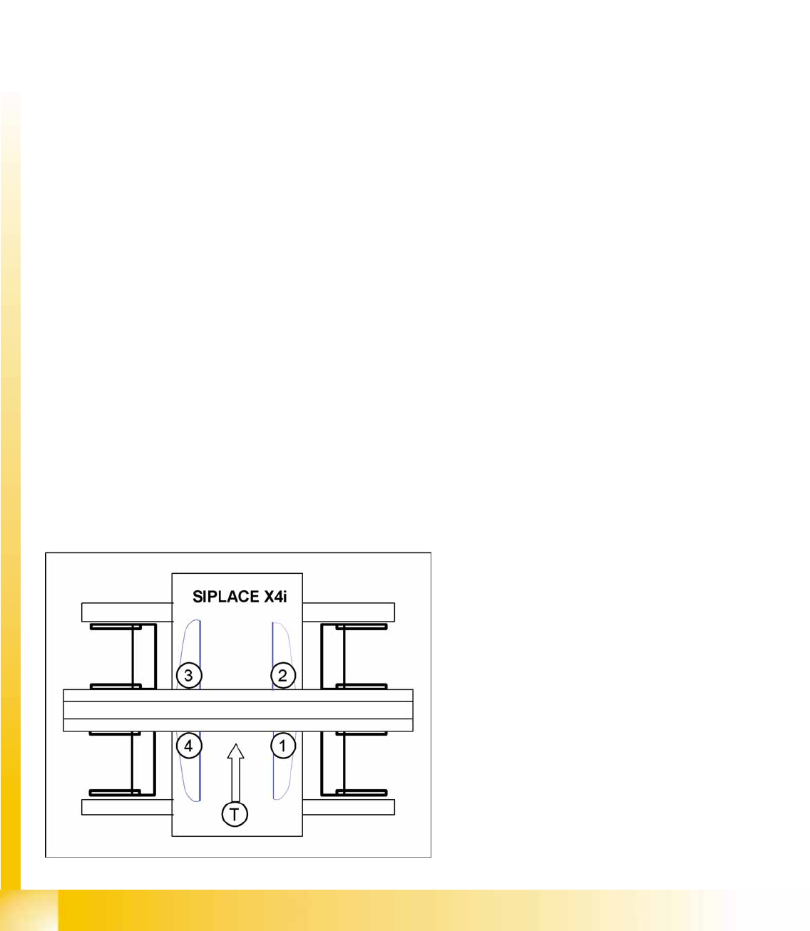
SIPLACE X4I:
Gantry 4 – position recognition with max. 3
fiducials
Gantry 2 – position recognition with 2 fiducials
Gantries 1 and 3 – dual position recognition
Legend
1: Gantry 1
2: Gantry 2
3: Gantry 3
4: Gantry 4
T: Transport direction
C&P20A
Board Recognition - Centering the Board Fiducials Pickup and Placement Cycle for C&P20A
Student Guide (FSE) SIPLACE X Series and X4I
Edition 01/2009 EN C&P20A
263
7.4.4 Board Recognition - Centering the Board Fiducials
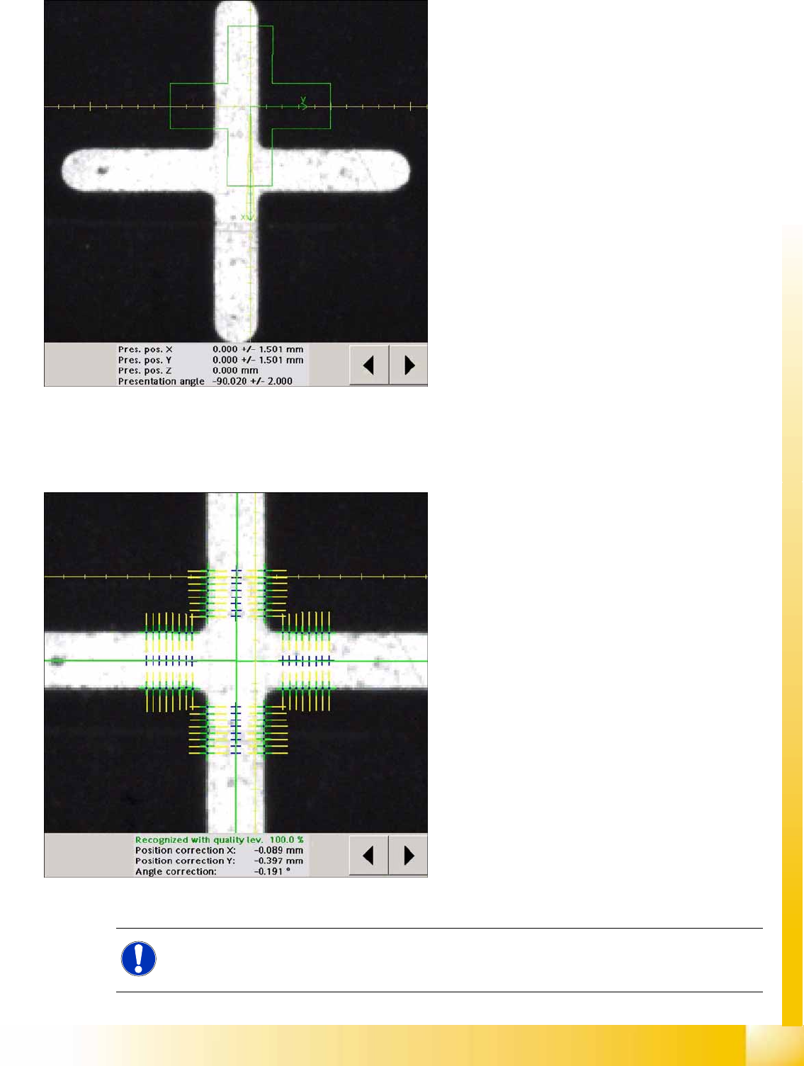
7-20: Board recognition run to target position of board
The fiducial is expected at this target position. The
PCB camera is moved from waiting position to this
fiducial position.
Board position recognition is performed before
the first component is picked up.
The gantry axes move the PCB camera to the
theoretical fiducial position. The camera takes
the picture of the first fiducial and the Vision
system calculates the center position.
7-21: Board recognition - centering the board fiducials
The centered fiducial now defines the actual
position of the board.
The camera records an image of the 2nd
fiducial and the Vision system calculates the
center position of this image.
The 2nd calculation is the deviation between
the target and the calculated fiducial position.
All board fiducials are optically centered with
this procedure.
This data is sent to the machine controller.
Corrected values are now calculated for the
X,Y and angular position of the board.
The gantry axes now move the placement
head to the first pickup position.
NOTE:
If synthetic fiducials are used, the procedure described above remains the same, although
inkspot recognition will now be performed after fiducial recognition.