00196044-05 - sg x und x4i fse_en.pdf - 第266页
C&P20A Pickup and Placement Cycle for C&P20A Picking Up component 11 S tudent Guide (FSE) SI PL ACE X Series and X4I C&P20A Edition 01/2009 EN 266 7.4.9 Picking Up component 1 1 7.4.10 Picking Up Compon ent 1…
C&P20A
Picking up component 1 Pickup and Placement Cycle for C&P20A
Student Guide (FSE) SIPLACE X Series and X4I
Edition 01/2009 EN C&P20A
265
7.4.7 Picking up component 1
The remaining nozzles now pick up the components as the star is stepped and turn these into the correct
centering angle, before they reach the component camera.
7.4.8 Picking Up component 11
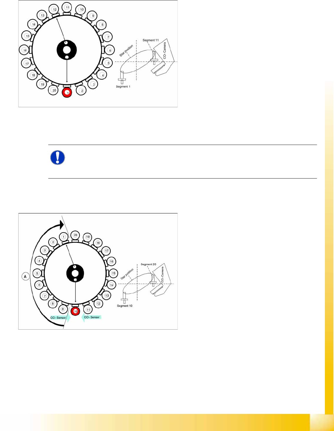
7-24: Picking up component 1
Star position 0°
Vision system: No action
Pickup/placement station: Picking up
component 1
Z Axis Down
Vacuum check for component pickup
Component sensor: direct measurement after
picking up the first component (applies
accordingly to all other segments)
Vacuum check after pickup: Check holding
force of the component on the nozzle.
NOTE:
All vacuum measurements during the placement process are performed in the background and
do not produce any error messages. The error messages concerning missing components etc.
are produced only by the component sensor.
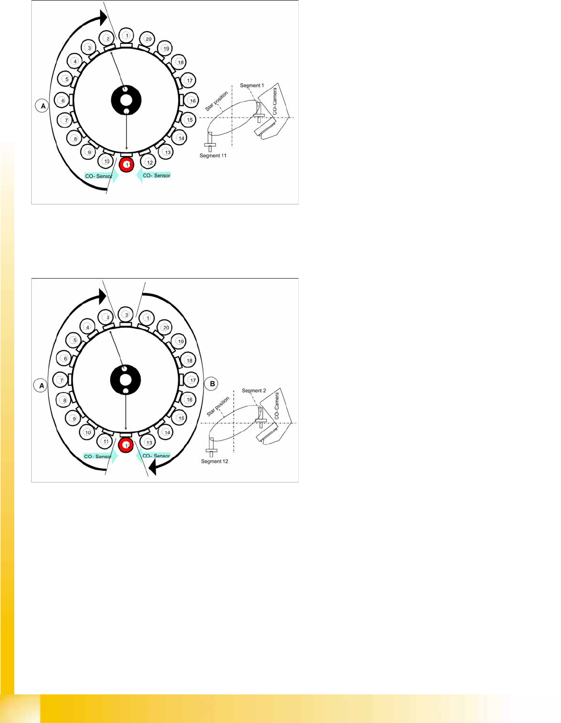
7-25: Picking Up component 11
Star position 162°
Vision system: "Prepare SIPLACE Vision for
optical centering".
Pickup/placement station: Pick up component
10
A : The components previously picked up are
rotated to the centering angle.
(centering angle [0°, 90°, 180°, 270°] =
placement angle in 90° steps)
Measurement of hold circuit for Segment 1
(output to measuring sensor)
C&P20A
Pickup and Placement Cycle for C&P20A Picking Up component 11
Student Guide (FSE) SIPLACE X Series and X4I
C&P20A Edition 01/2009 EN
266
7.4.9 Picking Up component 11
7.4.10 Picking Up Component 12
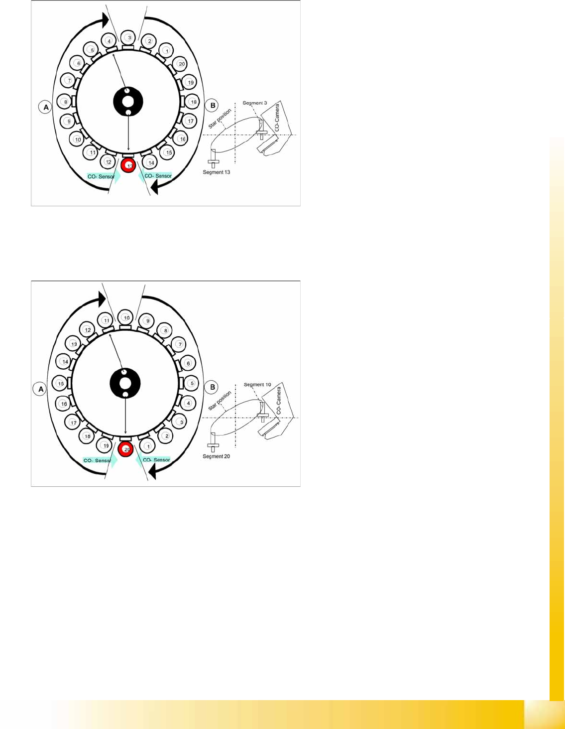
7-26: Picking Up component 11
Star position 180°
Vision system: Optical centering of component
on segment 1.
Pickup/placement station: Pick up component
11
A : The components previously picked up are
rotated to the centering angle. Empty nozzles
are turned to the next pickup angle.
Measurement of hold circuit for segment 2
7-27: Picking up component 11
Star position 198°
Vision system: Component at segment 2 of
this gantry is centered
Pickup/placement station: Picking Up
Component 12
A : The components previously picked up are
rotated to the centering angle, here.
B : The components are adjusted to their
placement angles.
C&P20A
Picking Up component 11 Pickup and Placement Cycle for C&P20A
Student Guide (FSE) SIPLACE X Series and X4I
Edition 01/2009 EN C&P20A
267
7.4.11 Picking Up component 11
7.4.12 Picking Up Component 20
7-28: Picking Up component 11
Star position 216°
Vision system: Optical centering of component
3
Pickup/placement station: Pick up component
13
A : The components previously picked up are
rotated to the centering angle, here.
B : The components are adjusted to their
placement angles.
Measurement of hold circuit for segment 4
The process continues with the remaining
components: picked up, centered and turned to
the correct or corrected placement angle.
7-29: Picking up component 11
Star position 342°
Vision system: Optical centering of component
10
Pickup/placement station: Pick up component
20
Communication with the changeover table:
cutter enabled
Synchronization: After picking up component
20, this gantry waits for permission to position
from the Y axis controller of the other gantry.
Component sensor: during the next star step,
component presence/ height check is
performed for segment 1.
A : The components previously picked up are
rotated to the centering angle, here.
B : The components are adjusted to their
placement angles.