00196044-05 - sg x und x4i fse_en.pdf - 第267页
C&P20A Picking Up component 11 Pickup and Placement Cycle for C&P20A S tudent Guide (FSE) SIPL ACE X Series and X4I Edition 01/2009 EN C&P20A 267 7.4.1 1 Picking Up component 1 1 7.4.12 Picking Up Compon ent …
C&P20A
Pickup and Placement Cycle for C&P20A Picking Up component 11
Student Guide (FSE) SIPLACE X Series and X4I
C&P20A Edition 01/2009 EN
266
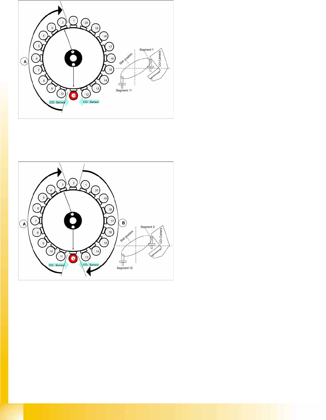
7.4.9 Picking Up component 11
7.4.10 Picking Up Component 12
7-26: Picking Up component 11
Star position 180°
Vision system: Optical centering of component
on segment 1.
Pickup/placement station: Pick up component
11
A : The components previously picked up are
rotated to the centering angle. Empty nozzles
are turned to the next pickup angle.
Measurement of hold circuit for segment 2
7-27: Picking up component 11
Star position 198°
Vision system: Component at segment 2 of
this gantry is centered
Pickup/placement station: Picking Up
Component 12
A : The components previously picked up are
rotated to the centering angle, here.
B : The components are adjusted to their
placement angles.
C&P20A
Picking Up component 11 Pickup and Placement Cycle for C&P20A
Student Guide (FSE) SIPLACE X Series and X4I
Edition 01/2009 EN C&P20A
267
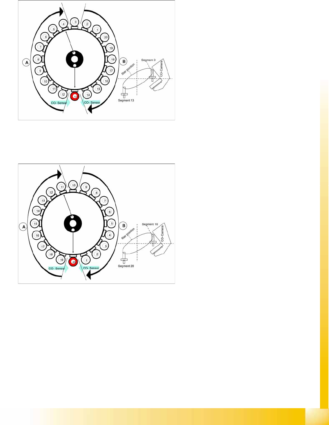
7.4.11 Picking Up component 11
7.4.12 Picking Up Component 20
7-28: Picking Up component 11
Star position 216°
Vision system: Optical centering of component
3
Pickup/placement station: Pick up component
13
A : The components previously picked up are
rotated to the centering angle, here.
B : The components are adjusted to their
placement angles.
Measurement of hold circuit for segment 4
The process continues with the remaining
components: picked up, centered and turned to
the correct or corrected placement angle.
7-29: Picking up component 11
Star position 342°
Vision system: Optical centering of component
10
Pickup/placement station: Pick up component
20
Communication with the changeover table:
cutter enabled
Synchronization: After picking up component
20, this gantry waits for permission to position
from the Y axis controller of the other gantry.
Component sensor: during the next star step,
component presence/ height check is
performed for segment 1.
A : The components previously picked up are
rotated to the centering angle, here.
B : The components are adjusted to their
placement angles.
C&P20A
Pickup and Placement Cycle for C&P20A Checking the Component Sensor of the Component at Segment 1
Student Guide (FSE) SIPLACE X Series and X4I
C&P20A Edition 01/2009 EN
268
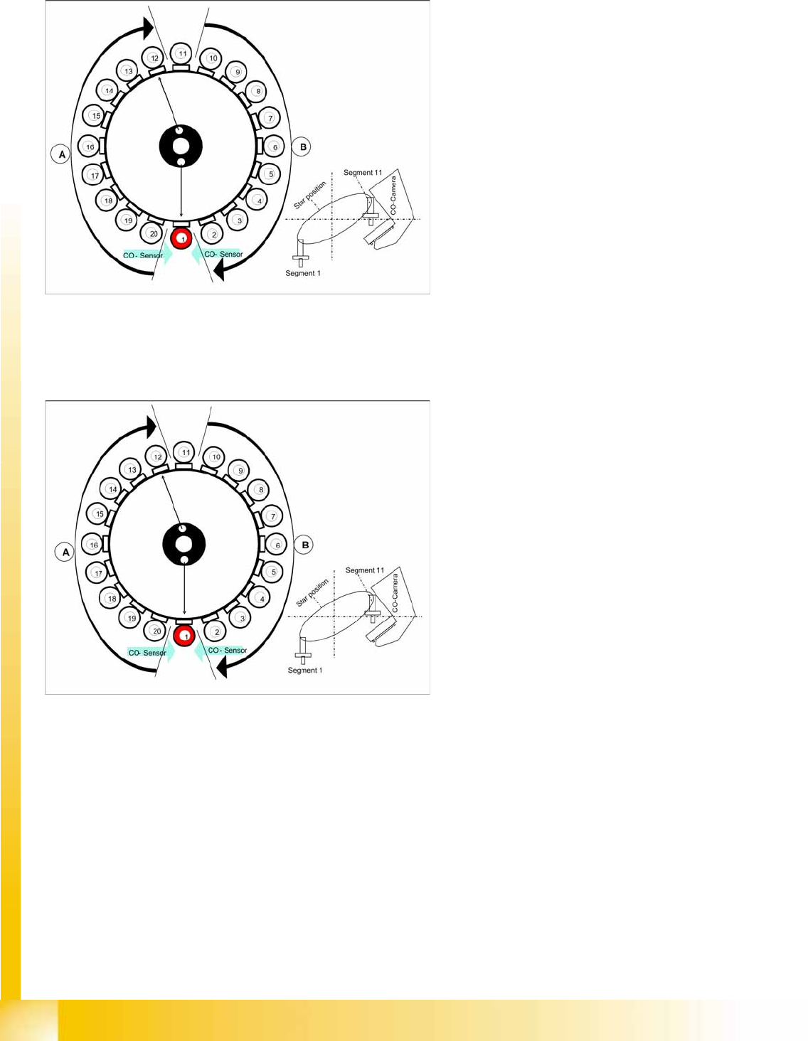
7.4.13 Checking the Component Sensor of the Component at Segment 1
7.4.14 Placing Component 1
7-30: Checking the component before placement
Star turns to -> 360° (identical with 0° position)
Measurement with component sensor: When the
star axis has turned to 360.000 digits, component
1 is again in placement position.
Vacuum check: Holding force for component
present?
Z axis starts to move downwards and then
The component sensor checks the presence
or the component height at segment 1.
The length measured before placement must
exceed nozzle length + component height -
component height tolerance.
If errors occur, the Z axis will be stopped and
moved back.
7-31: Placing component 11
Star position 0°
Vision system: Optical centering of component
11
Pickup/placement station: Z axis moves
downwards to place component 1.
A : The components previously picked up are
rotated to the centering angle, here.
B : The components are adjusted to their
placement angles.