00196044-05 - sg x und x4i fse_en.pdf - 第277页
C&P20A Board Descriptions for C&P20A Settings S tudent Guide (FSE) SIPL ACE X Series and X4I Edition 01/2009 EN C&P20A 277 Intermediate Distributor - C&P20 7-43: Intermediate distributor - position of the…
C&P20A
Settings Board Descriptions for C&P20A
Student Guide (FSE) SIPLACE X Series and X4I
C&P20A Edition 01/2009 EN
276
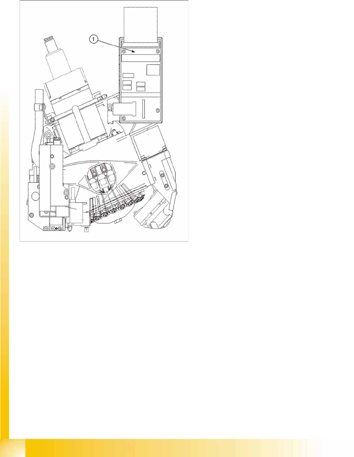
7.5.1.2 Intermediate Distributor Arrangement for C&P20A
7-42: Intermediate distributor for C&P20A
Legend
1. Intermediate distributor board
C&P20A
Board Descriptions for C&P20A Settings
Student Guide (FSE) SIPLACE X Series and X4I
Edition 01/2009 EN C&P20A
277
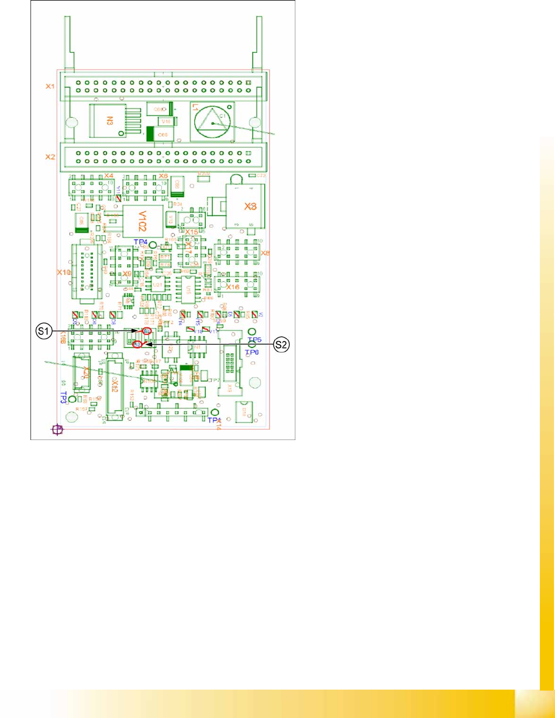
Intermediate Distributor - C&P20
7-43: Intermediate distributor - position of the sockets
Legend
The following supply voltages and signals are
routed by the intermediate distribution board to the
individual placement head modules or to the head
board:
Connector X1, 40-pole: Connected to plug X1
on the head adapter board
Connector X2, 40-pole: Connected to plug X2
on the head adapter board
Connector X3: Connection for the star motor
Connector X4: Connection for the star
incremental encoder
Connector X6: Connection for the Z axis
incremental encoder
Connector X8: Connection for the Z motor
Connector X9: Connection for the component
sensor
Connector X12: Connection for pressure
control valve
Connector X14: Test connector X14_3: +5 V/
X14_4: +15 V/X14_5: -15 V/X14_7:24 V for
DP motors
Connector X15: Connection for return unit
Connector X16: Internal CAN bus C&P20
C&P20A
Settings Board Descriptions for C&P20A
Student Guide (FSE) SIPLACE X Series and X4I
C&P20A Edition 01/2009 EN
278
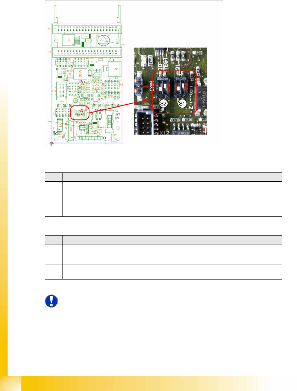
Switch setting S1, S2
7-44: Intermediate distributor - position of DIP switch
S1 (default setting: bold)
S2 (default setting: bold)
No. Function Switch setting = 0 (open) Switch setting = 1 (closed)
S1.1 Z-down sensor: Switch
on LED
LED only switched on during operation LED always on (test mode e.g. for
detection of nozzle suspension with
oscillo.)
S1.2 Z-down sensor: Activate
LED in clocked mode
LED is activated in clocked mode during
operation
LED is always switched on
during operation
No. Function Switch setting = 0 (open) Switch setting = 1 (closed)
S2.1 CAN test Normal operation: 1-wire head CAN
bus only with motherboard - ready for
operation
Test mode: operation without
motherboard possible
S2.2 CAN ID switchover -
pressure control valve
CAN ID active for pressure control valve
0x6B0
CAN ID for pressure control
valve 0x6B8 (test mode)
NOTE:
The default switch setting is always printed in bold.