00196044-05 - sg x und x4i fse_en.pdf - 第280页
C&P20A Settings Overview of Spare Parts and Settings for C&P20A S tudent Guide (FSE) SI PL ACE X Series and X4I C&P20A Edition 01/2009 EN 280 7.5.2 Overview of Sp are Part s and Settin gs for C&P20A Descr…
C&P20A
Board Descriptions for C&P20A Settings
Student Guide (FSE) SIPLACE X Series and X4I
Edition 01/2009 EN C&P20A
279
LEDs - meanings:
Test points:
Test connector X14:
No. Function On Off
D3 +5 V Present Not present
D4 Z down Triggered Not triggered
D5 Z down reset Reset Not reset
D6 +15 V Present Not present
D7 +24 V_IN
D8 -15 V Present Not present
V2 Z return valve Activated (down/bottom) Not activated (up/top)
V11 Enable pressure control valve Error - pressure control valve Pressure control valve OK
V14 +24 V Present Not present
V15 +24 V_DP Switched on Switched off
V16/17 Voltage GND
No. Function
TP1 GND
TP3 Voltage pressure signal - pressure control valve - internal
TP4 Output voltage I/U converter Z down
TP5 Z down
TP6 Z up/Z down reset
Pin Signal
1CAN_RX
2GND
3+5 V
4+15 V
5 -15 V
6 X2_11
724V_DP
8 Z up/Z down reset
C&P20A
Settings Overview of Spare Parts and Settings for C&P20A
Student Guide (FSE) SIPLACE X Series and X4I
C&P20A Edition 01/2009 EN
280
7.5.2 Overview of Spare Parts and Settings for C&P20A
Description (spare part) Tools Values
Component Camera Calibration component and
Allen wrench
Measuring the digital component camera.
Digital vacuum generator Caccia Firmware download possible
Read unit Z axis (not spare part) Feeler gauge 0.4 mm 0.4 mm between incremental encoder and
incremental scale.
Complete Z drive
Incremental encoder
Linear motor (for Siemens
service only)
Allen wrench During assembly, press the Z drive against the
stops.
Determining the star and Z zero point
correction.
Z axis return unit Move the return unit actuator to its end stop, so
that the Z axis is in the top position and the star
can be rotated.
Light barrier Z axis down (not
spare part)
Test probe 1.0 mm Distance 1.0 mm.
Component sensor (for Siemens
service only)
Check function
Firmware download possible
Silencer 10 mm open-end wrench None
Vacuum holding circuit, complete
Vacuum generator
Silencer
Special screw
10 mm open-end wrench
Allen wrench
Segment with DP drive Nippers with plastic tips
Allen wrench
Settings: none; firmware download possible;
calibrate segment offset (top, bottom).
Star carrier, complete (not spare
part)
Allen wrench Determining the star and Z zero point correction.
E/D transformer (collector ring),
comp. (for Siemens service only)
Allen wrench Determining the Z and star zero point correction.
C&P20A
Setting the Nozzle Changer for C&P20A Settings
Student Guide (FSE) SIPLACE X Series and X4I
Edition 01/2009 EN C&P20A
281
7.5.3 Setting the Nozzle Changer for C&P20A
7.5.3.1 Nozzle station
The height of the nozzle reject unit must be set to 140.0 +\-0.3 mm. Measurement follows the same
procedure as that for the nozzle changer .
See also:
J
7.5.3 Setting the Nozzle Changer for C&P20A [
J
281]
J
7.5.3 Setting the Nozzle Changer for C&P20A [
J
281]
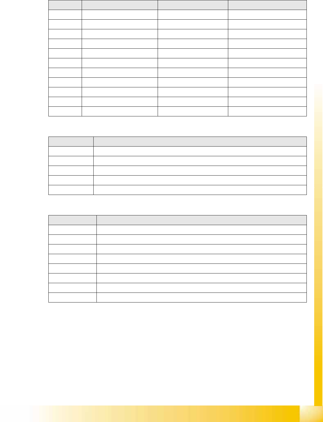
7-45: Setting the nozzle changer for C&P20A
Legend
1. Measuring scale
2. Top edge of the X axis lower linear guide
3. Fitting surface for nozzle changer
In order to guarantee the safety gap between the
head (component sensor) and nozzle changer, the
contact surface of the nozzle changer on the
docking unit is set to a distance of 150.0 mm +/-
0.2 mm to the X axis linear guidance, with a
measuring scale. The height of the fitting surface
on the docking unit is adjusted with the help of
shim rings. The nozzle changer can then be fitted.
NOTE: Fitting the nozzle changer
When fitting the nozzle changer, make sure that the component reject tray can be removed and
Ensure that the screws you are using are not too long, as these might jam the reject tray.
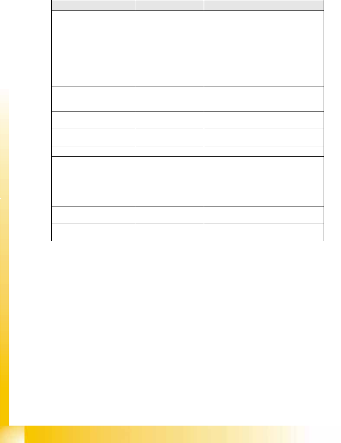
The C&P20 reject unit is equipped with a device
for checking the seat of the nozzles on the
segments, after a nozzle change. The nozzle
station also features an air blast valve, which
removes the components externally with a blast of
air. If components are not rejected via the blast air
pulse by the pressure control valve, the placement
head will automatically move to the nozzle station
to reject the components there.
Legend
1. Check nozzle seat
2. Nozzle reject