00196044-05 - sg x und x4i fse_en.pdf - 第287页
C&P20A Pneumatic Plan for Nozzle Changer Nozzle changer S tudent Guide (FSE) SIPL ACE X Series and X4I Edition 01/2009 EN C&P20A 287 7.6.5 Pneumatic Plan for Nozzle Changer 7-50: Pressure air supply for the nozzl…
C&P20A
Nozzle changer Addressing Nozzle Changers with CAN Node Module
Student Guide (FSE) SIPLACE X Series and X4I
C&P20A Edition 01/2009 EN
286
7.6.4 Addressing Nozzle Changers with CAN Node Module
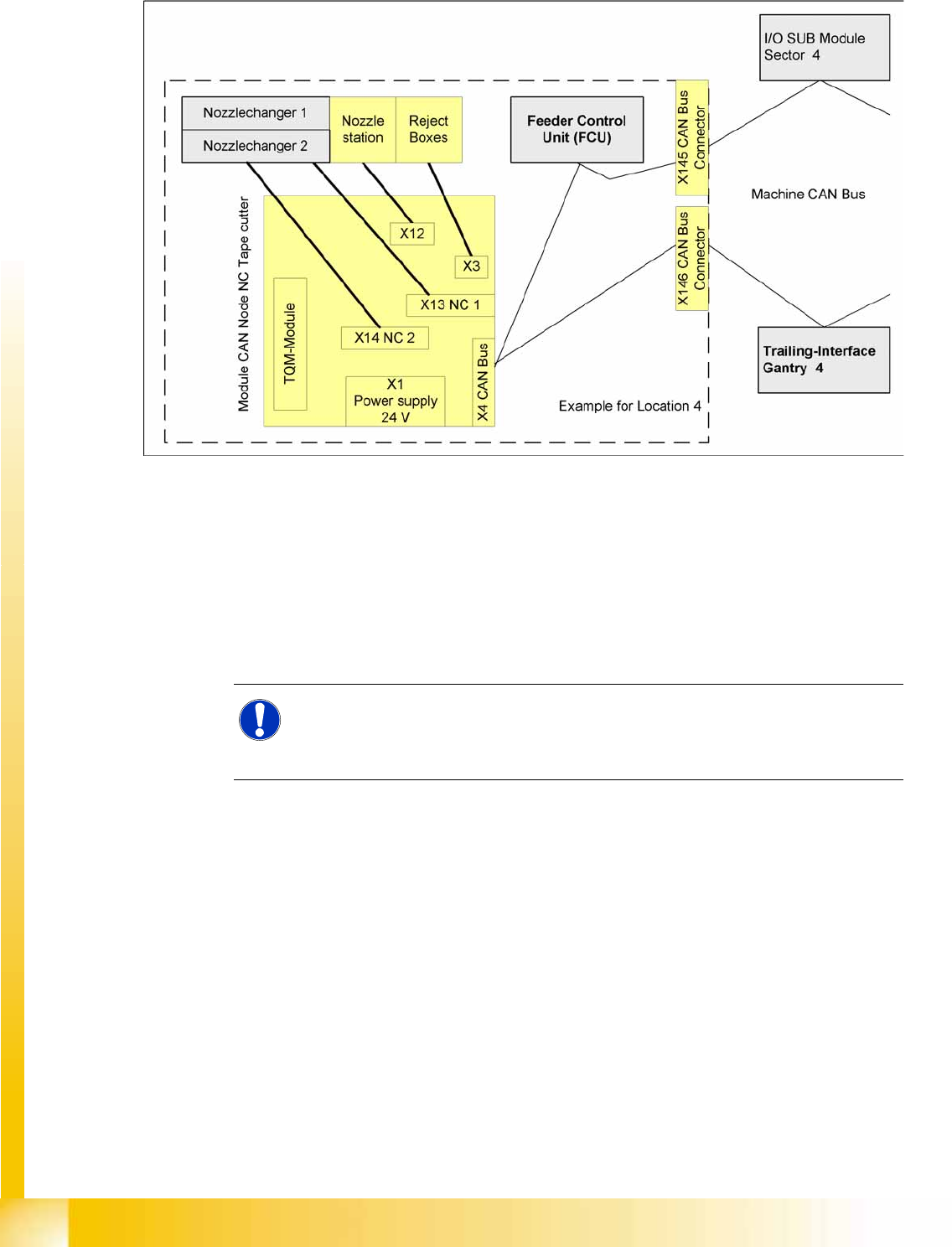
7-49: Nozzle changer control
The nozzle changer is controlled via a so-called CAN node. This is integrated into the machine CAN bus.
The CAN Node NC tape cutter module has the following tasks:
1. Cutter control (see Chapter Component Handling)
2. Nozzle changer control (row 1/2)
3. Valve control in the nozzle station
4. Sensor monitoring at the component and nozzle reject bin
See also:
J
4.3.11 Tape Cutter and Nozzle Changer - Communication [
J
127]
NOTE:
Old nozzle changers, which were addressed via the one wire bus, are not able to
communicate via the CAN nodes. The new NC can be addressed via one wire and
CAN nodes.
C&P20A
Pneumatic Plan for Nozzle Changer Nozzle changer
Student Guide (FSE) SIPLACE X Series and X4I
Edition 01/2009 EN C&P20A
287
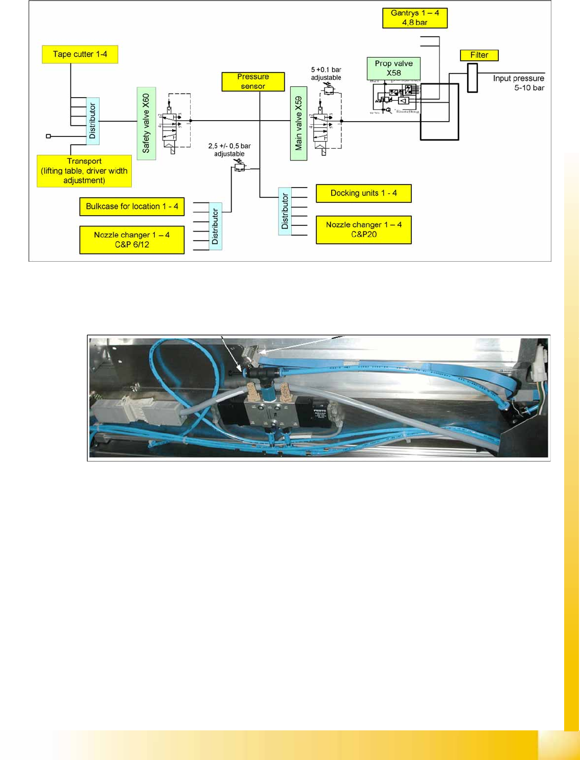
7.6.5 Pneumatic Plan for Nozzle Changer
7-50: Pressure air supply for the nozzle changer
The compressed air supply of 4.5 bar for the C&P20 nozzle changer is connected via a T-piece (see
diagram below). The optional 2nd magazine carrier is supplied with compressed air via another Y piece.
(Not for X4I)
7-51: Compressed air connection (T-piece) for nozzle changer
C&P20A
Axis Control Overview of Axis Control for Star, Z and DP Axis
Student Guide (FSE) SIPLACE X Series and X4I
C&P20A Edition 01/2009 EN
288
7.7 Axis Control
7.7.1 Overview of Axis Control for Star, Z and DP Axis
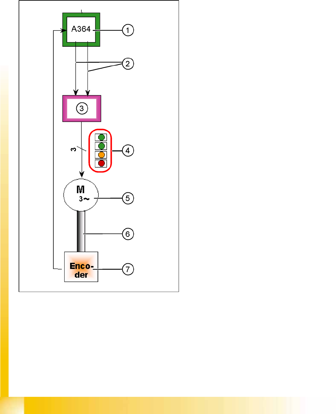
7-52: Example: Star axis control system
The closed-loop control system for control of the
head axes consists of the following parts. The
differences between the head axes will be
explained later in this chapter.
Axis Controller Board A364
Servo card (SDS for the Z axis, TBS for the
star axis)
Motor
Measurement system (incremental scale and
encoder)
Legend
1. Axis Controller Board A364
2. Control signals I target "W" and I target "U"
3. Servo amplifier
4. LEDs on servo board:
– GREEN: Power supply ON
– GREEN: Servo enable, if the enable signal
has been received from the axis board.
– YELLOW: Display R.M.S. current limiter
shorter than 2.5 s.
– RED: Error: overvoltage, overcurrent,
overtemperature longer than 2.5 sec.
5. 3 phase AC motor.
6. Between the motor and the incremental
encoder there is a fixed mechanical
connection.
7. Incremental encoder: transmits the exact
position of the axis. The track signals are the
only feedback signals for the axes.
The servo board controls the motor directly.