00196044-05 - sg x und x4i fse_en.pdf - 第288页
C&P20A Axis Control Overview of Axis Control for Star, Z and DP Axis S tudent Guide (FSE) SI PL ACE X Series and X4I C&P20A Edition 01/2009 EN 288 7.7 Axis Control 7.7.1 Overview of Axis Cont rol for St ar , Z an…
C&P20A
Pneumatic Plan for Nozzle Changer Nozzle changer
Student Guide (FSE) SIPLACE X Series and X4I
Edition 01/2009 EN C&P20A
287
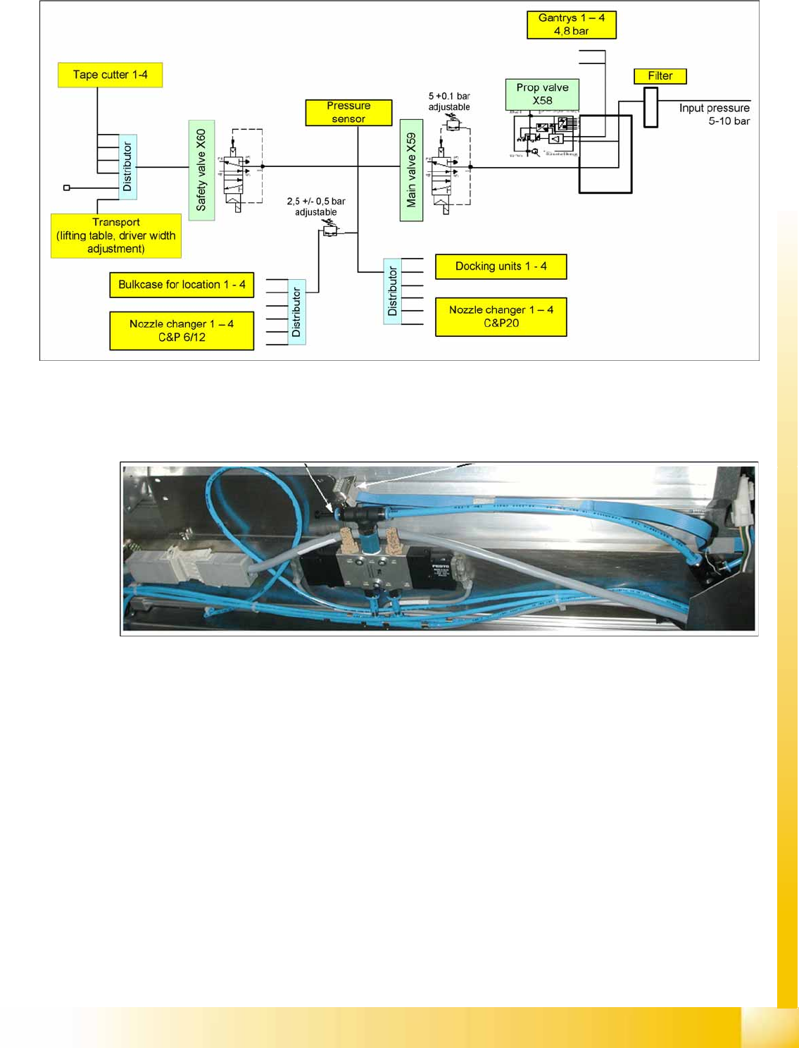
7.6.5 Pneumatic Plan for Nozzle Changer
7-50: Pressure air supply for the nozzle changer
The compressed air supply of 4.5 bar for the C&P20 nozzle changer is connected via a T-piece (see
diagram below). The optional 2nd magazine carrier is supplied with compressed air via another Y piece.
(Not for X4I)
7-51: Compressed air connection (T-piece) for nozzle changer
C&P20A
Axis Control Overview of Axis Control for Star, Z and DP Axis
Student Guide (FSE) SIPLACE X Series and X4I
C&P20A Edition 01/2009 EN
288
7.7 Axis Control
7.7.1 Overview of Axis Control for Star, Z and DP Axis
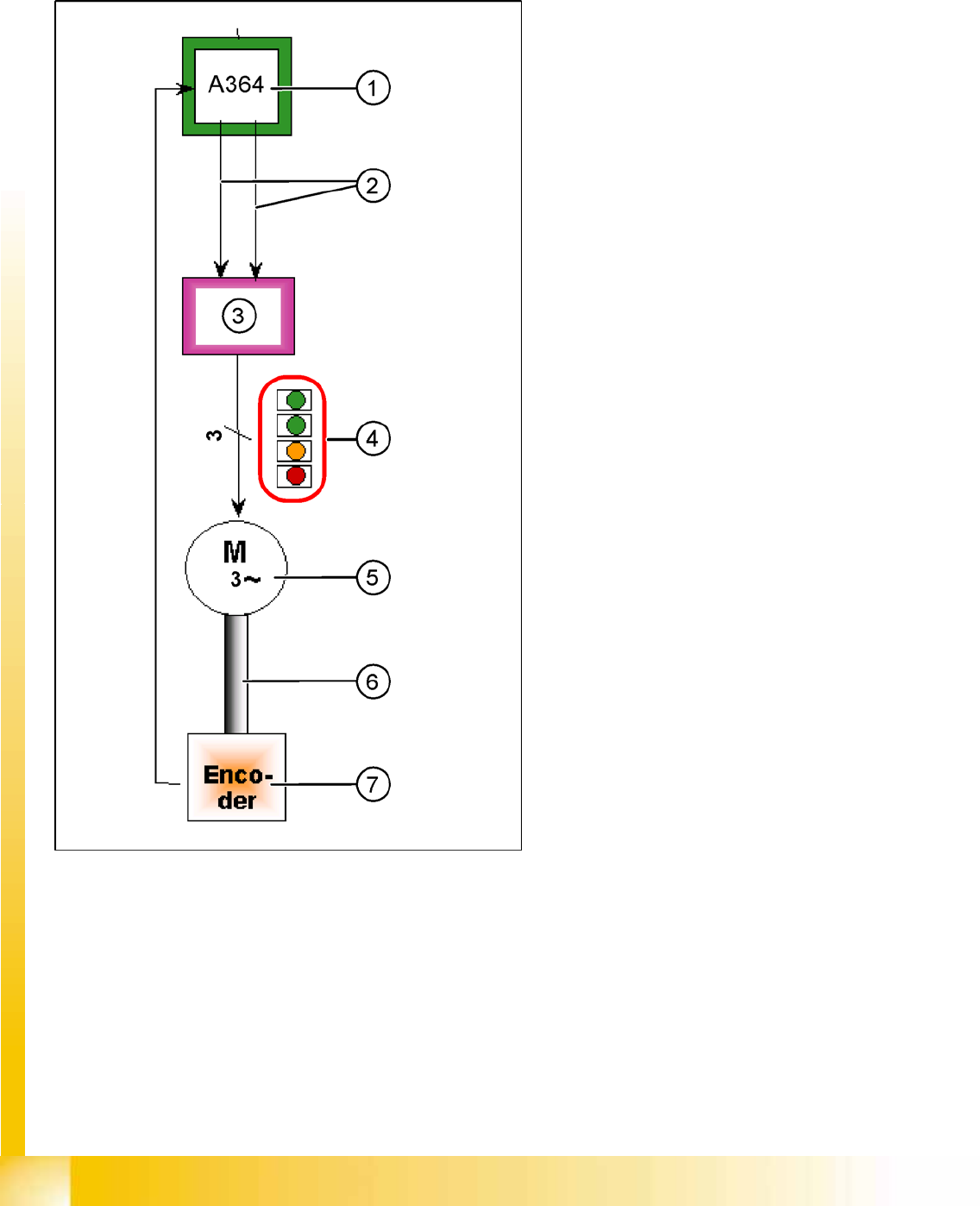
7-52: Example: Star axis control system
The closed-loop control system for control of the
head axes consists of the following parts. The
differences between the head axes will be
explained later in this chapter.
Axis Controller Board A364
Servo card (SDS for the Z axis, TBS for the
star axis)
Motor
Measurement system (incremental scale and
encoder)
Legend
1. Axis Controller Board A364
2. Control signals I target "W" and I target "U"
3. Servo amplifier
4. LEDs on servo board:
– GREEN: Power supply ON
– GREEN: Servo enable, if the enable signal
has been received from the axis board.
– YELLOW: Display R.M.S. current limiter
shorter than 2.5 s.
– RED: Error: overvoltage, overcurrent,
overtemperature longer than 2.5 sec.
5. 3 phase AC motor.
6. Between the motor and the incremental
encoder there is a fixed mechanical
connection.
7. Incremental encoder: transmits the exact
position of the axis. The track signals are the
only feedback signals for the axes.
The servo board controls the motor directly.
C&P20A
Track Signals for Head Axes Axis Control
Student Guide (FSE) SIPLACE X Series and X4I
Edition 01/2009 EN C&P20A
289
7.7.1.1 Positioning Time for C&P20A
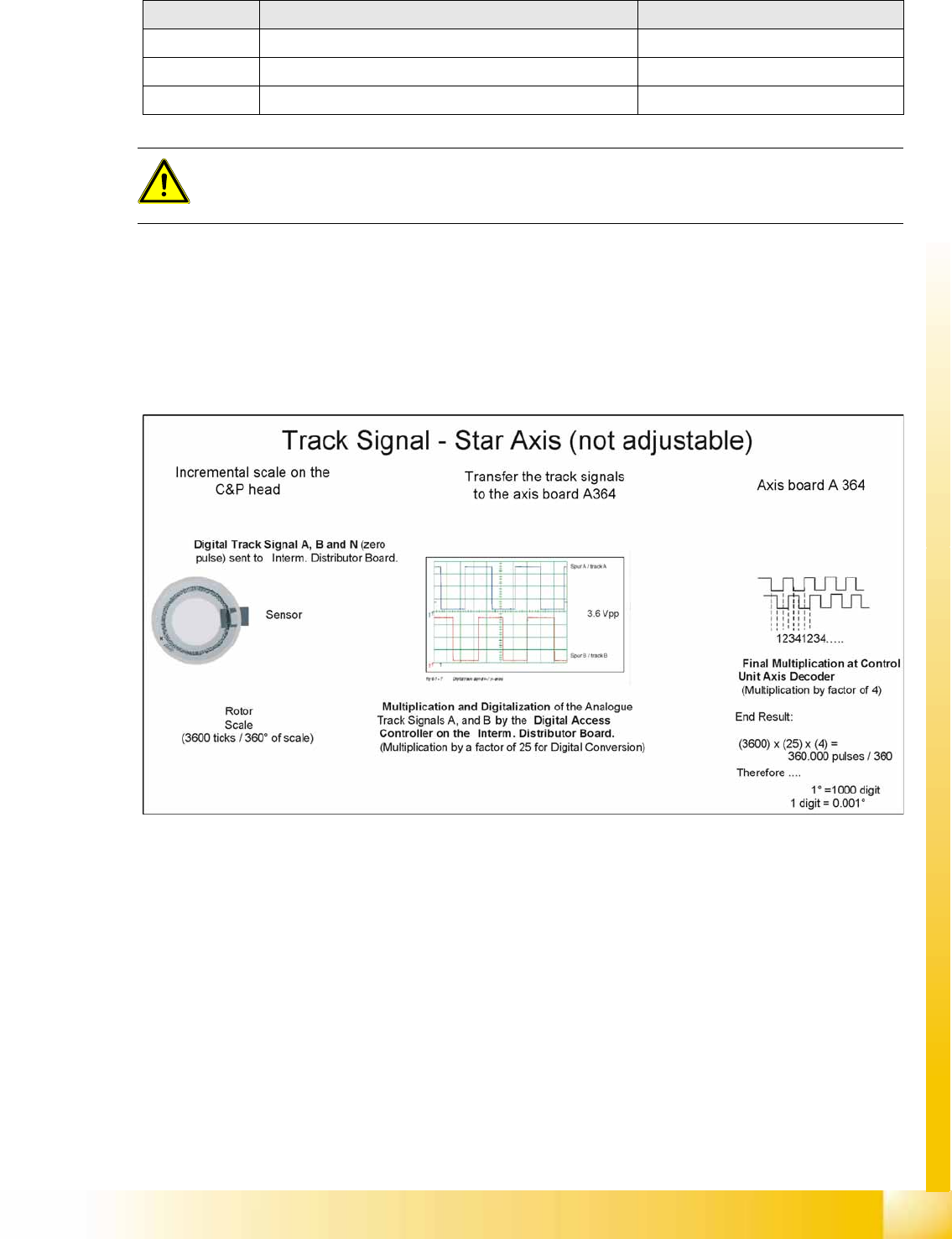
7.7.2 Track Signals for Head Axes
The track signals play a greater role with the new drive concept for X (HF) machines. They are
responsible for the exactly and precise positioning of the axes and are used as the only feedback signal
in the closed-loop control system, meaning that they have an important influence on the axis dynamics.
7.7.2.1 Preparing the Track Signals
Axis Mode/range/ Positioning time
Star Axis continuous run/1 step (18°) 28.5 ms +/-0.5 ms
Z Absolute, free space /20,000 digits 10,000 µm Target 16.7 ms+/-1ms
DP Rotation of 180° Max. 300 ms
ATTENTION:
The positioning times in the table do not apply during the placement or pickup procedures.
These times refer to the continuous axis run of an axis.