00196044-05 - sg x und x4i fse_en.pdf - 第293页
C&P20A Axis Control of Z A xis Axis Control S tudent Guide (FSE) SIPL ACE X Series and X4I Edition 01/2009 EN C&P20A 293 7.7.4 Axis Control of Z Axis 7.7.4.1 Checking the Z Axis Dy namics 7.7.4.2 Measurement Setu…
C&P20A
Axis Control Star Axis Control System
Student Guide (FSE) SIPLACE X Series and X4I
C&P20A Edition 01/2009 EN
292
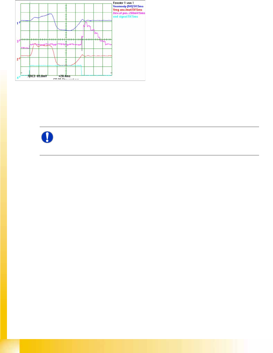
7.7.3.4 Signal Example with the Vnom. Output
The star axis dynamics are checked in the permanent star step mode. A motor phase current is emitted
at the Vnominal output of the axis test box.(control signal 1). The uncommutated current setpoint signal
(signal 3) shows no increased friction values for the axis.
The positioning time for the star axis is 28.5 ms +/-0.5 ms C&P20A.
7-55: Dynamic signals for star axis of C&P20A
Legend
The signals from top to bottom:
Star phase motor current Iu measured at
Vnom output
Uncommutated current signal Vreg (or PIN at
axis adapter)
Deviation of position
End signal
NOTE: C&P20A
If these dynamics should be significantly slower or if the uncommutated current signal should
deviate considerably, check the star axis mechanics for damage or the servo amplifier/axis
controller (other boards connected to the star) for electrical damage.
C&P20A
Axis Control of Z Axis Axis Control
Student Guide (FSE) SIPLACE X Series and X4I
Edition 01/2009 EN C&P20A
293
7.7.4 Axis Control of Z Axis
7.7.4.1 Checking the Z Axis Dynamics
7.7.4.2 Measurement Setup
The Z-C&P20A positioning time for 15 mm is 20 ms in both directions. The positioning time for the 0-
20000 digit (10 mm) range should be 16.7 ms.
Position the gantries so that the Z axis is above the calibration component position.
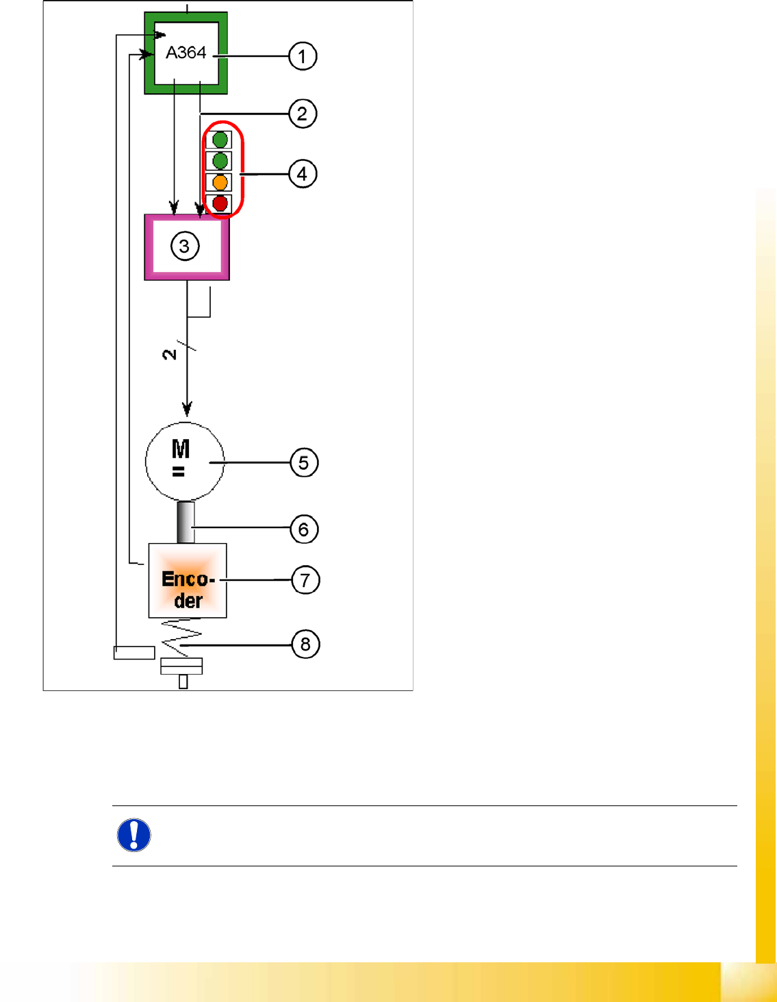
7-56: Axis control of Z axis
The C&P20A Z axis is driven via a 3~ AC linear
motor. This activation is via two control signals
phase from the VC3 controller Itarget "W" and I-
target "U". The intermediate circuit voltage is
approx. 24V.
Legend
1. Axis Controller Board A364
2. Control signal I nom "W"
3. Servo amplifier
4. LEDs on servo board:
– Power supply ON
– Servo enable, if the enable signal has
been received from the axis board.
– Display R.M.S. current limiter shorter than
2.5 s.
– Error: Overvoltage, overcurrent,
overtemperature or nominal current
overshoot longer than 2.5 sec.
5. 3~ AC (DC) motor.
6. Between the motor and the incremental
encoder there is a fixed mechanical
connection.
7. Incremental encoder: transmits the exact
position of the axis (track signals).
8. Elastic mech. connection (belt) and light
barrier down, for fast recognition of the lower
position.
The servo board controls the 3-phase AC (DC)
motor directly.
NOTE:
The measurement procedure follows the same preparations and procedures as for the star axis.
C&P20A
Axis Control Axis Control of Z Axis
Student Guide (FSE) SIPLACE X Series and X4I
C&P20A Edition 01/2009 EN
294
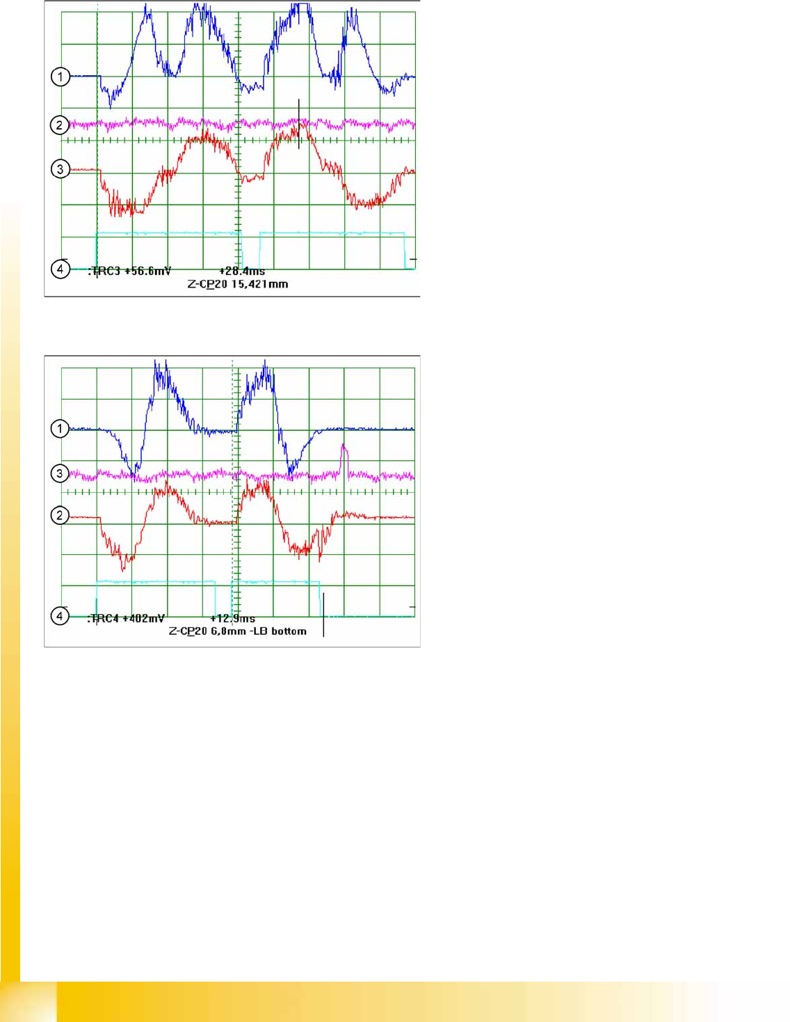
7.7.4.3 Signal Example C&P20A Z Axis with the Control Signal at Vnom. Output
7-57: Z axis dynamic signals for C&P20A -15.4 mm range
Legend
1. Motor phase current signal (
Vnom output
)
2. Uncommutated current signal V
reg
3. Deviation of position
4. End signal
15.4 mm positioning with the Z axis into free space
7-58: Z axis dynamic signals for C&P20A - calibration tool pocket
Legend
1. Motor phase current signal (V
nom
output)
, positioning up in each case
2. Uncommutated current signal V
reg
, positioning downwards
3. Deviation of position
4. End signal
6.8 mm positioning with the Z axis into the
calibration tool pocket