00196044-05 - sg x und x4i fse_en.pdf - 第296页
C&P20A Room for Your Sketches and Notes Axis Control of DP Axis S tudent Guide (FSE) SI PL ACE X Series and X4I C&P20A Edition 01/2009 EN 296 7.8 Room for Y our Sketches and Notes
C&P20A
Axis Control of DP Axis Axis Control
Student Guide (FSE) SIPLACE X Series and X4I
Edition 01/2009 EN C&P20A
295
7.7.5 Axis Control of DP Axis
7.7.5.1 Checking the DP Axis Dynamics
7.7.5.2 Measurement Setup
X The SIEMENS service technician uses special software to start a continuos function run.
X The value shown for each individual DP drive should be less than 300 ms at 180°.
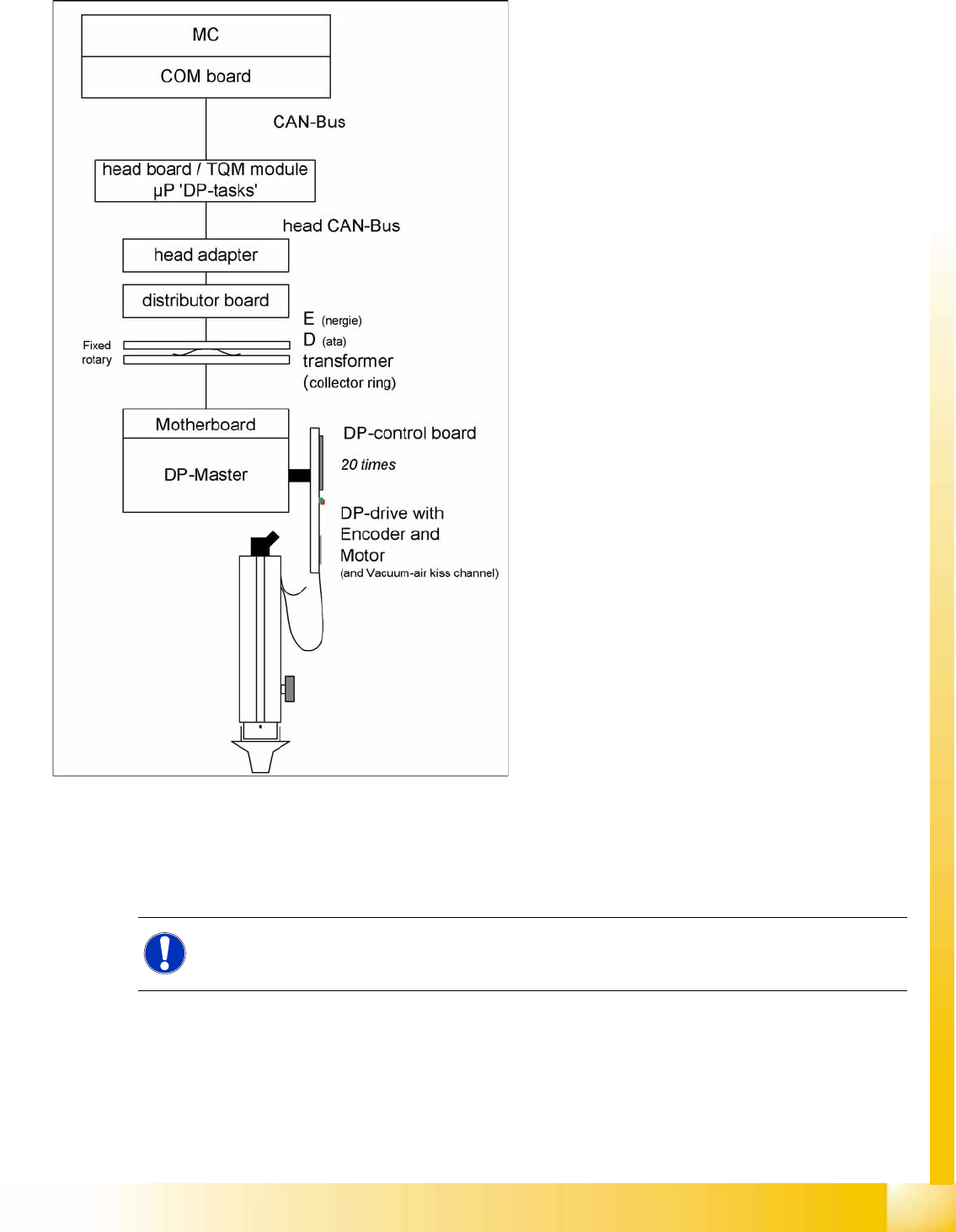
7-59: Axis control of DP axis for a C&P20A segment
The DP axes of the C&P20A segments are
positioned by a DP masterboard and an "on
board" direct control unit. The control system uses
CAN Bus at the respective head board. The
intermediate circuit voltage is approx. 24V. Each
segment has its own DP drive for rotating
independently of the others.
The station software transmits the activation
commands via the machine CAN Bus to the head
processor.
This activates via 4 DP tasks and the head CAN
bus system with activation commands, via the
head adapter, intermediate distributor and the
collector rings of the E/D transformer at the
motherboard with the DP master.
The DP motor control in the segment is handled at
the DP control board with the help of count pulse
from the integrated HALL incremental encoder.
NOTE:
There are no measurement points accessible on the C&P20A rotary drives.

C&P20A
Room for Your Sketches and Notes Axis Control of DP Axis
Student Guide (FSE) SIPLACE X Series and X4I
C&P20A Edition 01/2009 EN
296
7.8 Room for Your Sketches and Notes

C&P20A
Axis Control of DP Axis Room for Your Sketches and Notes
Student Guide (FSE) SIPLACE X Series and X4I
Edition 01/2009 EN C&P20A
297