00196044-05 - sg x und x4i fse_en.pdf - 第303页
Collect, Pick and Place Head (CPP) Overview of Parts Overview S tudent Guide (FSE) SIPL ACE X Series and X4I Edition 01/2009 EN Collect, Pick and Place Head (CPP) 303 8.2.7 Overview of Part s 8.2.7.1 Front plate 8.2.7.2 …

Collect, Pick and Place Head (CPP)
Overview Special Features of CPP Head
Student Guide (FSE) SIPLACE X Series and X4I
Collect, Pick and Place Head (CPP) Edition 01/2009 EN
302
8.2.5 Special Features of CPP Head
There are various placement modes: C&P mode, P&P mode and mixed mode.
Symmetrical head design: The head can be fitted on the left or right.
Component spectrum for component 01005 – 50x40 mm
Component height max. 11.5 mm
The holding circuit has one venturi nozzle for each segment.
→ No more interference between the segments.
Each segment has its own valve. Each segment can therefore be switched off separately.
→ This reduces the air consumption.
Each segment has its own motor with incremental measuring system.
→ The segments can be rotated independently of one another.
The light barrier down is integrated into each segment.
→ This leads to a high placement reliability. There is no need to adjust the light barrier down. This
design is more robust, since a movable cable is not required.
A digital pressure control valve enables faster switching times between vacuum and air blast.
The component sensors in the pickup&place position are more robust. The prisms have mechanical
protection.
→ This leads to a high placement reliability.
Robust nozzle interface and nozzle magazine
Nozzle types 20xx and 28xx with corresponding magazines
8.2.6 Principle of CPP Head
The CPP head functions according to the Collect&Place principle, like the C&P12 head, whereby the
additional operating modes Pick&Place and mixed mode help to extend the component spectrum.
Each segment is equipped with its own DP drive and an incremental measuring system, to allow
angle adjustment while the star is revolving.
The power and data are transferred from the stationary part of the head via a contact free ED
transformer to the control board (Single Core Solution - SCS) for the DP drives.
In addition, each DP drive has a light barrier Z down. Together with the secondary part of the linear
motor (Z axis), there is no cable which is moved with the Z movement.
The so/called valve terminal is used to switch the supply pressure on and off for each segment.
In the pickup and placement position, the Z axis moves with the complete DP drive unit upwards or
downwards.
In the pickup cycle, the vacuum is increased by the holding circuit, using a pressure control valve.
During placement, the vacuum is eliminated by the holding circuit, with an air blast, and the
components are blown off.
In the pickup/placement position, the standard component sensor is used to check the presence and/
or height of the components on the nozzle, both before and after pickup/placement.
Collect, Pick and Place Head (CPP)
Overview of Parts Overview
Student Guide (FSE) SIPLACE X Series and X4I
Edition 01/2009 EN Collect, Pick and Place Head (CPP)
303
8.2.7 Overview of Parts
8.2.7.1 Front plate
8.2.7.2 Pressure control valve (digital)
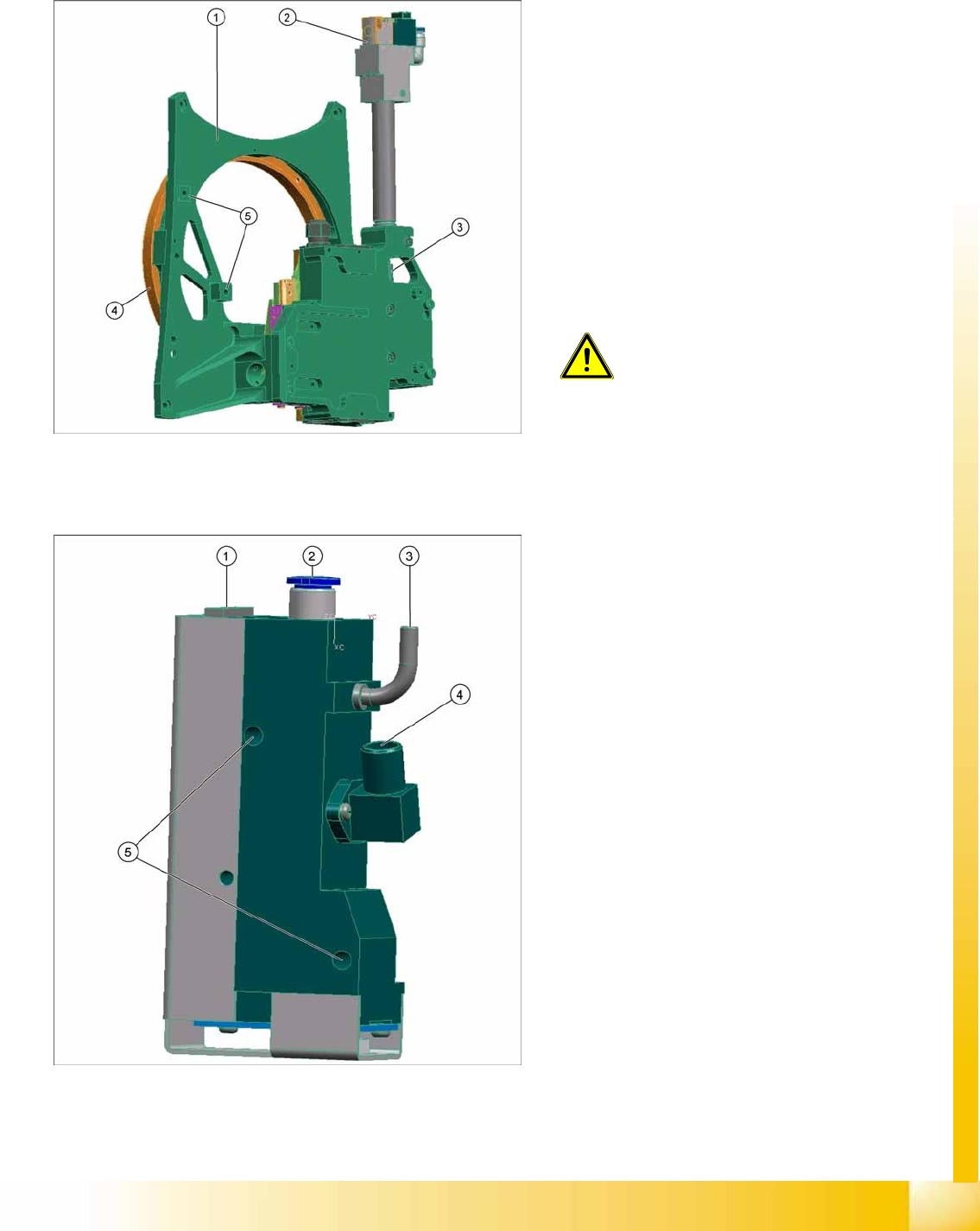
Legend
1. Front plate
2. Return cylinder
3. Z axis with jaws and measuring system
4. Raceway
5. Fixture for pressure control valve
Front plate
The front plate of the CPP head is fixed to the head
housing with four screws and needs to be
removed as a whole unit for service purposes.
ATTENTION:
Do not dismantle any of the
attachments from the front plate, as all
attachments are coordinated with one
another and require special settings.
Legend
1. Energy and data supply
2. Compressed air connection
3. Vacuum/air blast output for pickup/placement
circuit
4. Discharged air, for cooling the X motor
5. Fixture for fastening the pressure control valve
to the front plate
The pressure control valve supplies the
pickup/placement circuit with vacuum during
the pickup process and switches over to air
blast during placement.
The digital pressure control valve can be
adjusted infinitely between max. vacuum and
max. air blast in the pickup/place circuit.
The complete press control valve can be
replaced during service work.
Collect, Pick and Place Head (CPP)
Overview Overview of Parts
Student Guide (FSE) SIPLACE X Series and X4I
Collect, Pick and Place Head (CPP) Edition 01/2009 EN
304
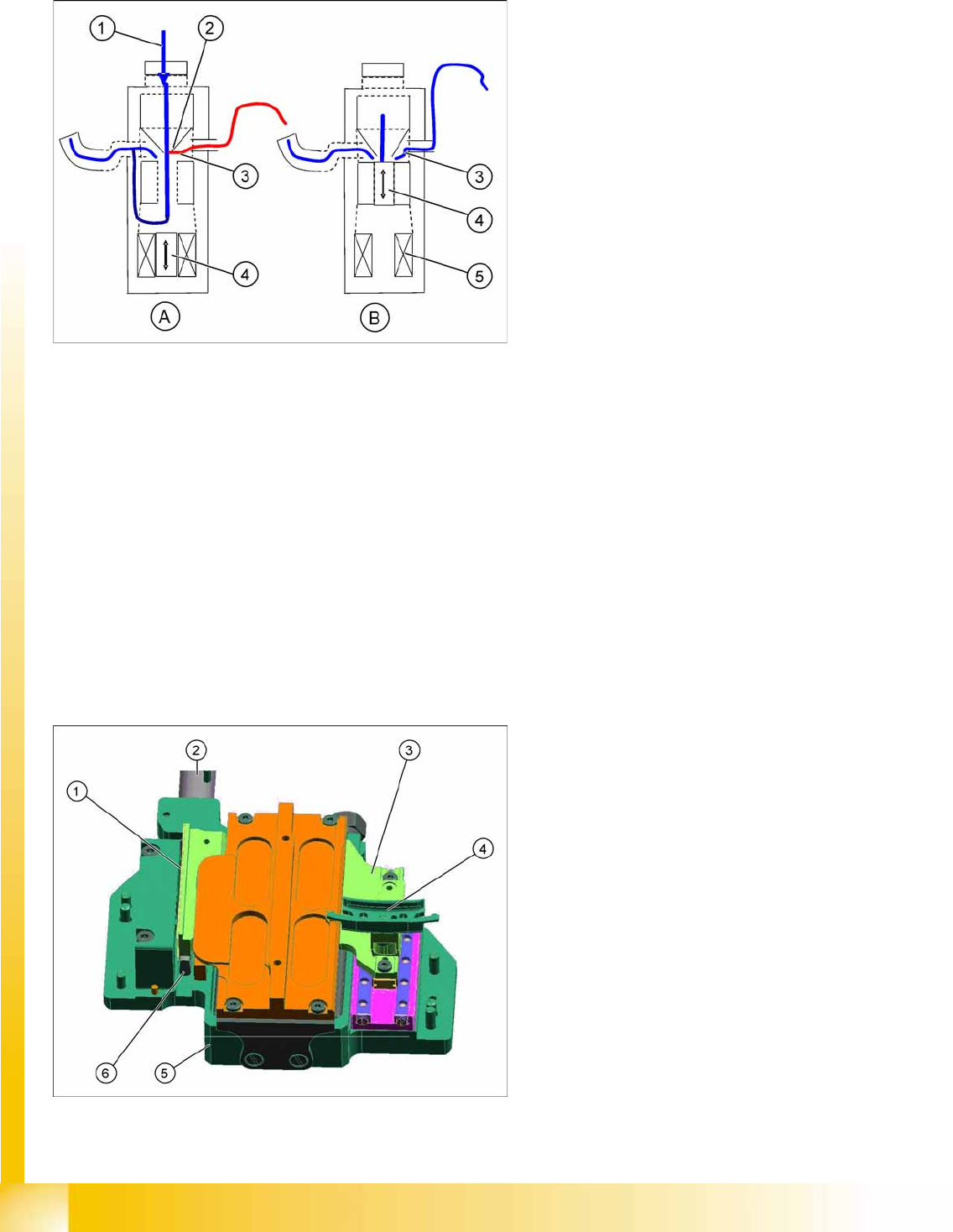
Pressure Control Valve - Function
8.2.7.3 Z axis
Legend
A : Piston setting for max. vacuum during pickup
B : Piston setting for air blast during placement
1. Compressed air inlet
2. Venturi nozzle
3. Vacuum or air blast outlet, depending on
piston setting
4. Pistons
5. Motor
After initialization, the piston is in a central
position, in which neither vacuum nor air blast
is applied to the nozzle.
During pickup, the piston is always in the
Open
position, so that maximum vacuum is
generated and is present at the nozzle. The
switchover time (pressure build up time)
between max. vacuum of –850 mbar to max.
air blast of +200 mbar ≤ 12ms.
The function
Early vacuum
should always be
switched on for the CPP head.
This ensures that max. vacuum is always
present at the nozzle and that the switchover
to air blast only occurs on placement.
Legend
1. Incremental measurement system, resolution
0.5 µm
2. Return unit
3. Secondary part with magnets
The secondary part is fitted to the Z axis.
4. Jaws
The jaws are fitted to the linear guidance of the
Z axis.
5. Linear motor, primary part
6. Actuator on the return unit