00196044-05 - sg x und x4i fse_en.pdf - 第311页
Collect, Pick and Place Head (CPP) Overview of Parts Overview S tudent Guide (FSE) SIPL ACE X Series and X4I Edition 01/2009 EN Collect, Pick and Place Head (CPP) 31 1 8.2.7.1 1 E/D T ransformer The energy and data tr …
Collect, Pick and Place Head (CPP)
Overview Overview of Parts
Student Guide (FSE) SIPLACE X Series and X4I
Collect, Pick and Place Head (CPP) Edition 01/2009 EN
310
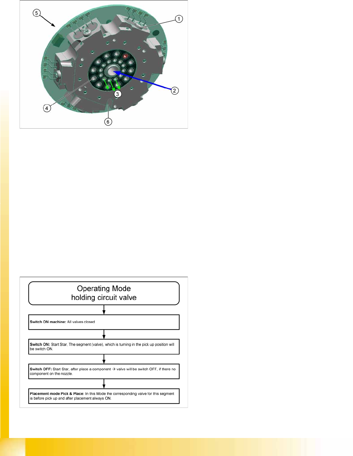
8.2.7.10 Valve terminal
The valve terminal consists of 12 valves (1), one for each segment.
The compressed air from the holding circuit (2) is distributed over 12 channels for the 12 segments. Each
of these channels has a valve. This enables the compressed air to be connected or disconnected for
each segment (3).
This means, After a component has been placed, the compressed air can be disconnected for this
segment.
Before picking up a component, the compressed air is connected again and vacuum is present at the
nozzle via the holding circuit with venturi nozzles. The disconnection of compressed air after placement
reduces the compressed air per placement head by approx. 40-50%.
The outer channels (4) are used to measure the holding circuit and supply the air blast or vacuum for the
pickup/placement circuit via the pressure control valve.
The valve terminal can be replaced during service work.
Holding Circuit Valve Functions
Legend
1. Valve (12x)
2. Compressed air from holding circuit
3. Inner channels - compressed air for the
segments
4. Outer channels
5. Contact free data transfer (receiver)
6. Flexprint for energy and data transfer to SCS
The valve terminal consists of 12 holding
circuit valves, which can be switched
independently at any time and in any star
position.
Switching on the valves means “throughput”:
Compressed air is present at the venturi
nozzles (voltage = 0V). If a valve should fail or
if it is without a voltage supply, vacuum is
always present at the holding circuit.
Switching off the valves means “valve closed”:
There is no compressed air present at the
venturi nozzle (24 V voltage is present). This
saves compressed air!
Collect, Pick and Place Head (CPP)
Overview of Parts Overview
Student Guide (FSE) SIPLACE X Series and X4I
Edition 01/2009 EN Collect, Pick and Place Head (CPP)
311
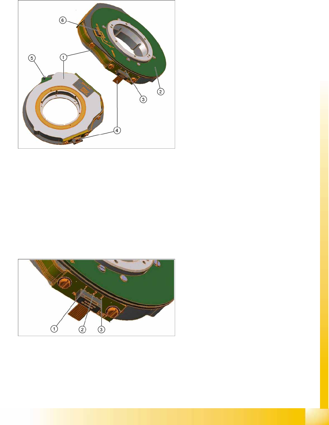
8.2.7.11 E/D Transformer
The energy and data transformer consists of a stationary and a rotating part.
The three sliding contacts transmit the direct current voltage (24V/4A).
Communication (the transmission of CAN Bus signals) is contactless. The transmitter is located on
the rear cover of the CPP head and the receiver module on the valve terminal.
The connector (4) supplies power and data to the intermediate distributor.
The centering pin fixes the stationary part in place via the rear cover of the CPP head.
The rotating part is fixed with five screws to the valve terminal.
The E/D transformer can be replaced during service work.
Energy transmission
Two transmission leads are needed to transmit the energy supply: P24V (1) and GND (2).
Another lead (3) (sliding contact) forms the connection between the rotating part and the housing
ground (ESD protection).
Legend
1. Stationary part
2. Rotating part
3. Sliding contacts (3x)
4. Connector for power supply
5. Centering pin
6. Interface to valve terminal
Legend
1. P24V
2. GND
3. ESD protection
Collect, Pick and Place Head (CPP)
Overview Overview of Parts
Student Guide (FSE) SIPLACE X Series and X4I
Collect, Pick and Place Head (CPP) Edition 01/2009 EN
312
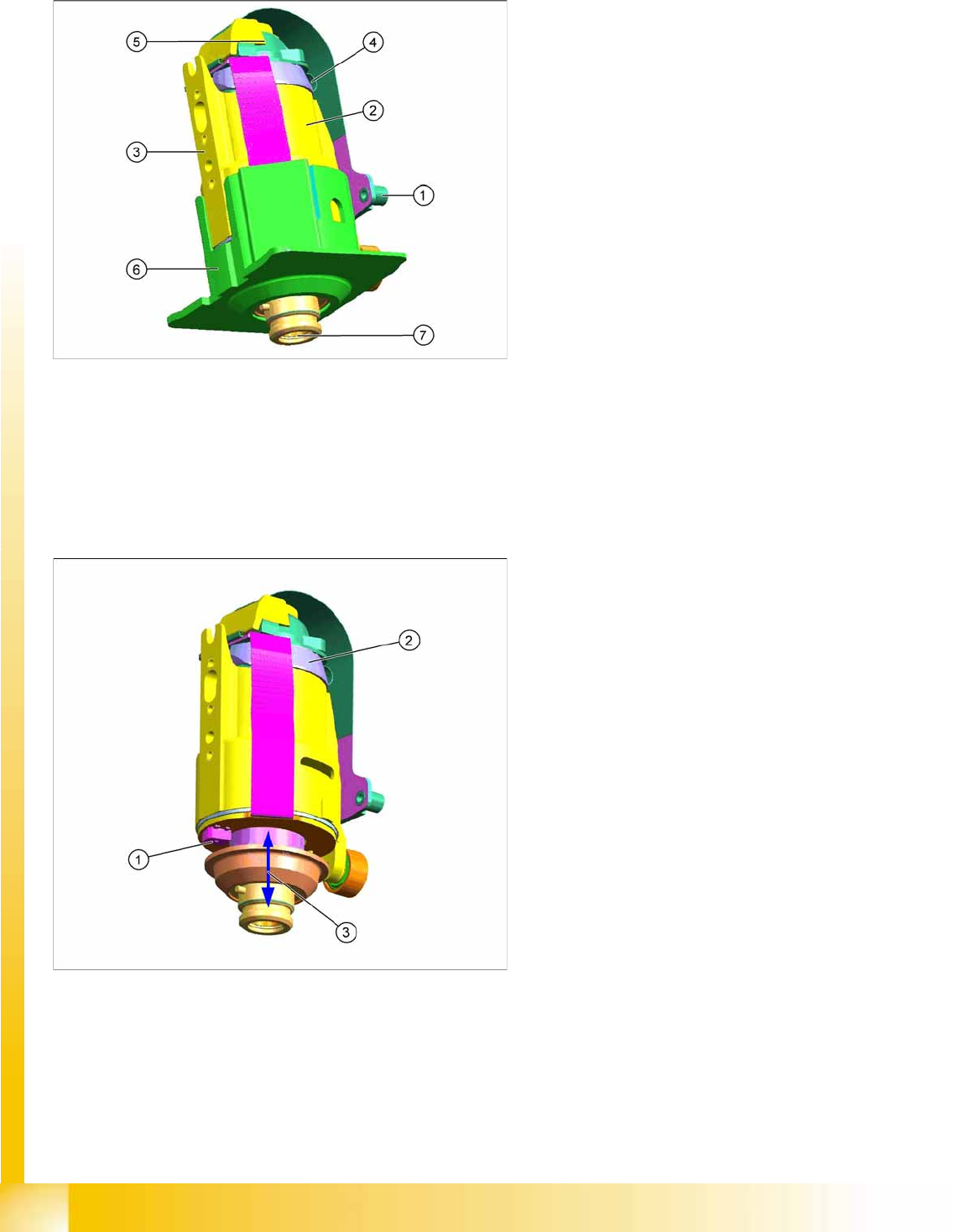
8.2.7.12 DP drive
The DP drive is responsible for turning the nozzles into the correct pickup position and the
component into the correct placement position.
The motor shaft of the DP axis provides vacuum and air blast to the nozzle.
The complete DP drive and the linear guidance can be replaced during service work.
DP drive function
Measuring system function
The measuring system consists of a glass disk with increments. This glass disk is fixed firmly to the motor
shaft.
The read unit evaluates, multiplies and digitalizes these increments. This actual position value is
continuously compared with the prescribed target value by the control circuit.
Legend
1. The connector is fitted and screwed to the
SCS control unit.
2. Motor
3. Fixture surface for screwing the linear
guidance into place
4. Vacuum connection
5. Measuring system
Resolution: 278 digits per degrees or
100.000 digits per revolution
6. Camera background (black) for DP drive
7. Nozzle interface
Legend
1. Light barrier down
2. Measuring system
3. Cushioning path for operating the light barrier
down
DP drive function
The DP drives are controlled by the SCS board, in
accordance with the counter pulse and set value
(pickup angle, placement angle and correction
angle after Vision).
The feedback about the position of the DC motor
is monitored by an incremental measuring system.