00196044-05 - sg x und x4i fse_en.pdf - 第313页
Collect, Pick and Place Head (CPP) Overview of Parts Overview S tudent Guide (FSE) SIPL ACE X Series and X4I Edition 01/2009 EN Collect, Pick and Place Head (CPP) 313 Light barrier down Each DP drive has its own light ba…
Collect, Pick and Place Head (CPP)
Overview Overview of Parts
Student Guide (FSE) SIPLACE X Series and X4I
Collect, Pick and Place Head (CPP) Edition 01/2009 EN
312
8.2.7.12 DP drive
The DP drive is responsible for turning the nozzles into the correct pickup position and the
component into the correct placement position.
The motor shaft of the DP axis provides vacuum and air blast to the nozzle.
The complete DP drive and the linear guidance can be replaced during service work.
DP drive function
Measuring system function
The measuring system consists of a glass disk with increments. This glass disk is fixed firmly to the motor
shaft.
The read unit evaluates, multiplies and digitalizes these increments. This actual position value is
continuously compared with the prescribed target value by the control circuit.
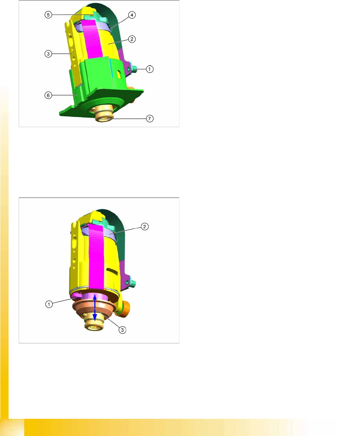
Legend
1. The connector is fitted and screwed to the
SCS control unit.
2. Motor
3. Fixture surface for screwing the linear
guidance into place
4. Vacuum connection
5. Measuring system
Resolution: 278 digits per degrees or
100.000 digits per revolution
6. Camera background (black) for DP drive
7. Nozzle interface
Legend
1. Light barrier down
2. Measuring system
3. Cushioning path for operating the light barrier
down
DP drive function
The DP drives are controlled by the SCS board, in
accordance with the counter pulse and set value
(pickup angle, placement angle and correction
angle after Vision).
The feedback about the position of the DC motor
is monitored by an incremental measuring system.
Collect, Pick and Place Head (CPP)
Overview of Parts Overview
Student Guide (FSE) SIPLACE X Series and X4I
Edition 01/2009 EN Collect, Pick and Place Head (CPP)
313
Light barrier down
Each DP drive has its own light barrier down sensor. When the Z axis springs into place, this sensor
sends a signal to the axis controller board or HCU. The "light barrier down" signal is directly linked to the
measurement signal of the Z axis incremental encoder.
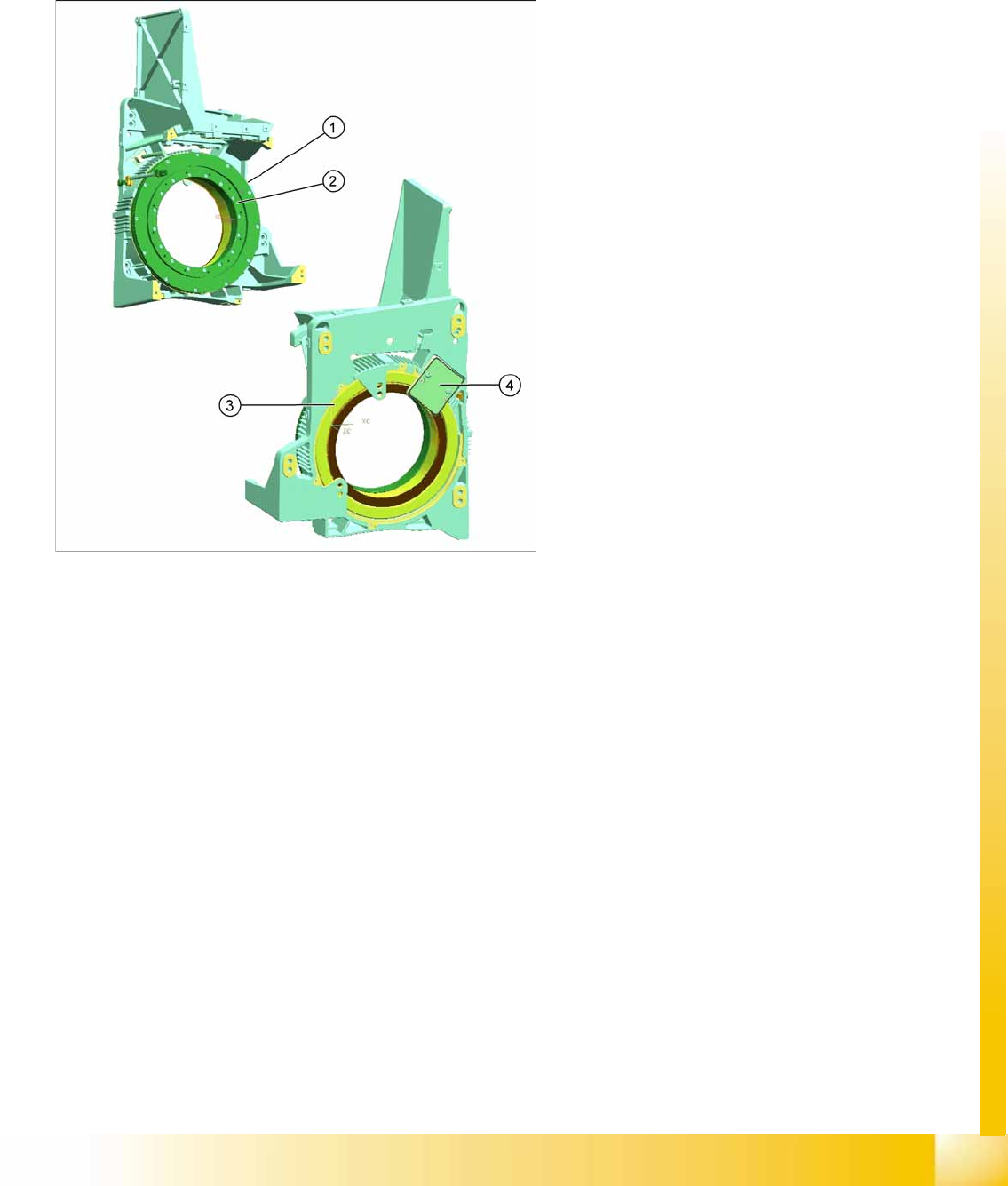
8.2.7.13 Star motor
Star Motor Function
The star motor is a brushless three-phase drive with sinus commutation.
An optical measurement system is used for both commutation and recognition of the rotary angle.
This supplies the track signals A, B and the zero pulse. The incremental measuring system has
3600 increment lines and one reference fiducial. By a multiplication of 25, 1 digit = 0.004° or
250 digits = 1°.
The motor is controlled with the help of these track signals. The actual position values are evaluated
on the controller assembly of the HCU (A364). The HCU power module (servo card) enhances
performance and is supplied with 2-phase current from the axis controller board. The third phase is
calculated automatically.
The supply line to the star motor has a board with EEPROM, in which the following data is stored:
– Production data (manufacturer, serial number, ...)
– Operating data (errors, travel cycles, ...)
– Machine data (motor data, travel profiles, zero point correction, max. and min. position)
Legend
1. Stator star motor
2. Rotor star motor
This is where the star carrier is fixed.
3. Incremental measuring system
4. Read unit incremental measuring system
The star motor is a direct current motor, in
which the coil is wound around the stator and
the magnets are taken up by the rotor.
The advantage of a torque motor is a much
faster reaction time coupled with a low lift (30°
steps). The motor functions contact free i.e.
there is no wear and tear.
The head casing also serves as the motor
casing.
The star motor is not a spare part and can not
be replaced.
Collect, Pick and Place Head (CPP)
Overview Overview of Parts
Student Guide (FSE) SIPLACE X Series and X4I
Collect, Pick and Place Head (CPP) Edition 01/2009 EN
314
8.2.7.14 Cover with Holding Circuit Sensor
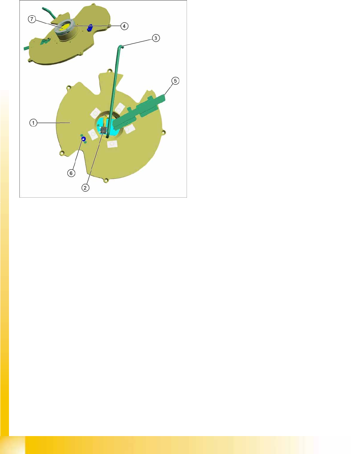
Legend
1. Rear head cover
The rear cover on the CPP head is fixed to the
head casing with 5 screws. The head therefore
needs to be dismantled from the gantry.
2. Holding circuit sensor
This cover has a board with holding circuit
sensor. This sensor monitors the vacuum in
the holding circuit.
3. Metal tube
This metal tube supplies the pickup/place
circuit with vacuum or air blast from the
pressure control valve.
4. Scmooth distributor disc
This is located inside the cover. This smooth
distributor disc has two drilled holes. One hole
leads to the pickup and place position. The
other hole is used to measure the vacuum in
the holding circuit at a certain position.
5. Data supply
This consists of a cable for the holding circuit
sensor board and another cable for the power
and data supply to the DP drives, valve
terminal and SCS.
6. Centering pin
The centering pin fixes the stationary part of
the E/D transformer.
7. Contact free data transfer (transmitter)