00196044-05 - sg x und x4i fse_en.pdf - 第317页
Collect, Pick and Place Head (CPP) Overview of Parts Reference run CPP head S tudent Guide (FSE) SIPL ACE X Series and X4I Edition 01/2009 EN Collect, Pick and Place Head (CPP) 317 8.3 Reference run CPP head 8-2: Referen…
Collect, Pick and Place Head (CPP)
Overview Overview of Parts
Student Guide (FSE) SIPLACE X Series and X4I
Collect, Pick and Place Head (CPP) Edition 01/2009 EN
316
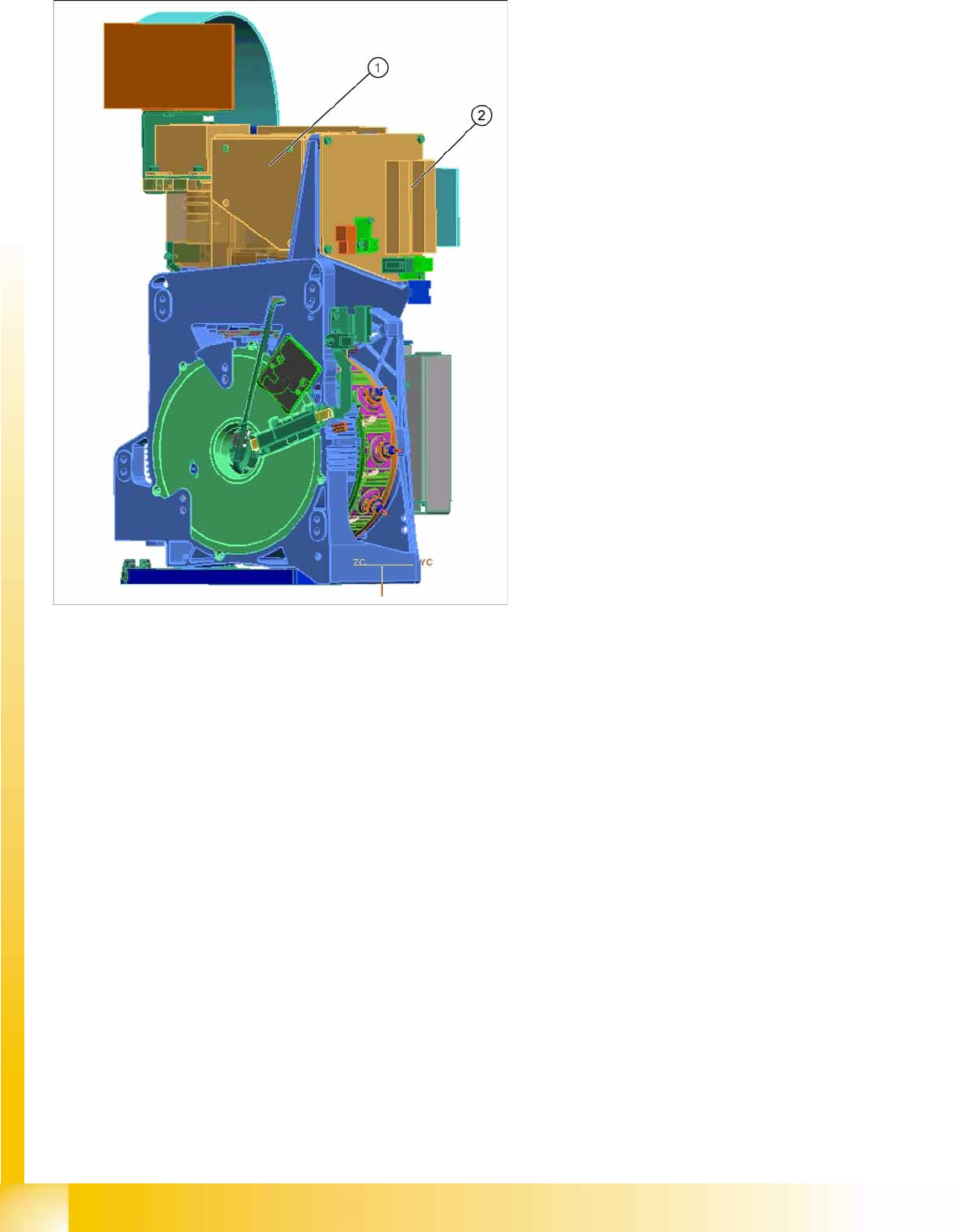
8.2.7.16 Component Camera
Legend
1. Component camera
2. Intermediate Distributor 2
Component camera (SST28 / SST29 /
SST38)
The component camera is fitted in the 12.00
position, as in the case of the C&P6/12 heads.
This camera is responsible for optically
recognizing the component and for calculating its
centerpoint.
The component camera evaluates the data
determined and calculates the offset between the
component centerpoint and the nozzle centerpoint
plus the angle in the placement position.
Collect, Pick and Place Head (CPP)
Overview of Parts Reference run CPP head
Student Guide (FSE) SIPLACE X Series and X4I
Edition 01/2009 EN Collect, Pick and Place Head (CPP)
317
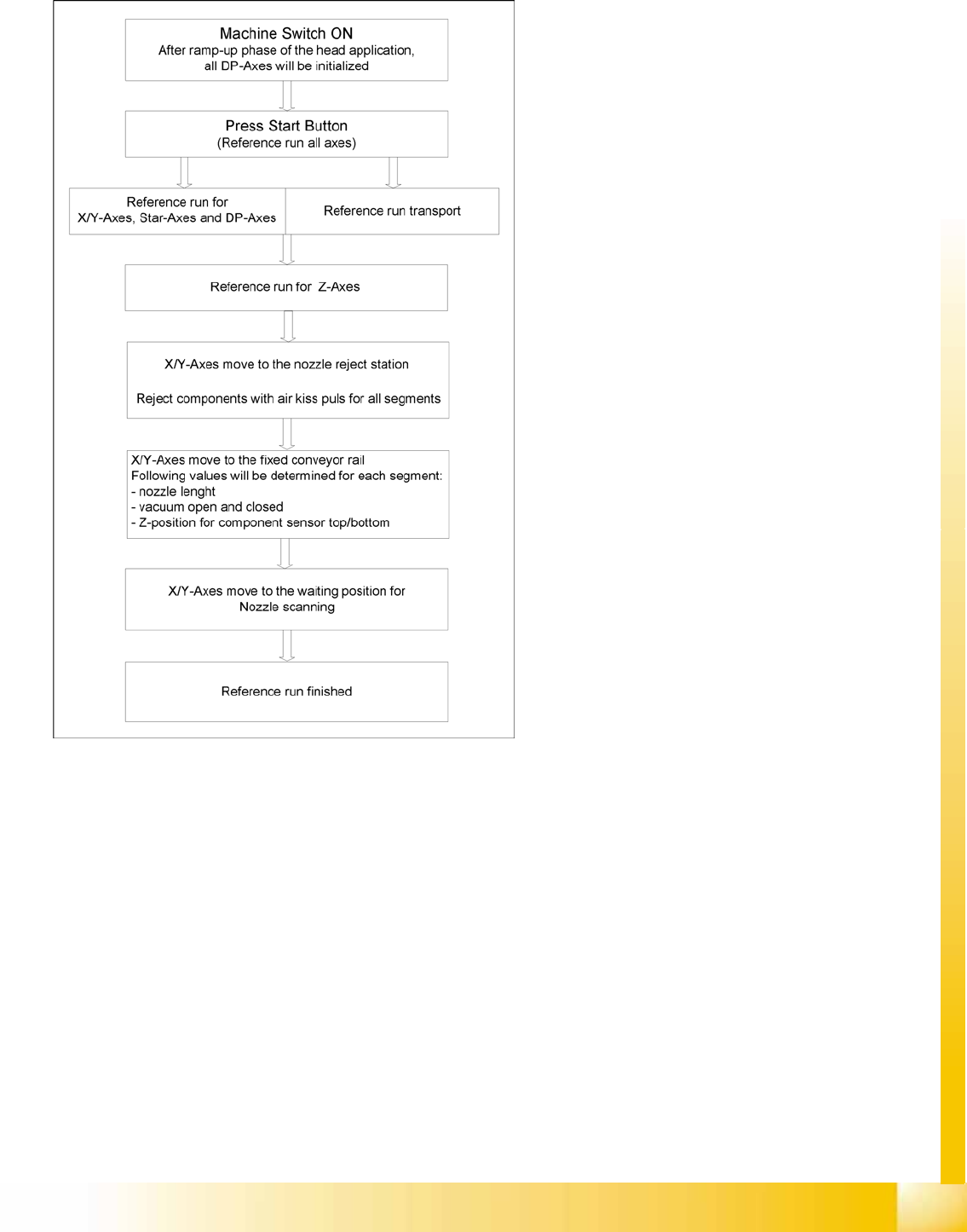
8.3 Reference run CPP head
8-2: Reference run CPP head
Description
The CPP head has a Z axis, a star axis and twelve
independent DP axes. All these axes need to be
initialized before placement begins. This ensures
that the control system knows where their actual
mechanical position is.
When the software is started, the embedded
software checks all subsystems and sends the
result to the superior control software.
The reference run is started by pressing the start
button (see adjacent flow diagram). The
processes have been optimized as far as possible
and can run parallel to one another (star and DP
axes plus initialization of conveyor).
Collect, Pick and Place Head (CPP)
Reference run CPP head Reference run Z axis
Student Guide (FSE) SIPLACE X Series and X4I
Collect, Pick and Place Head (CPP) Edition 01/2009 EN
318
8.3.1 Reference run Z axis
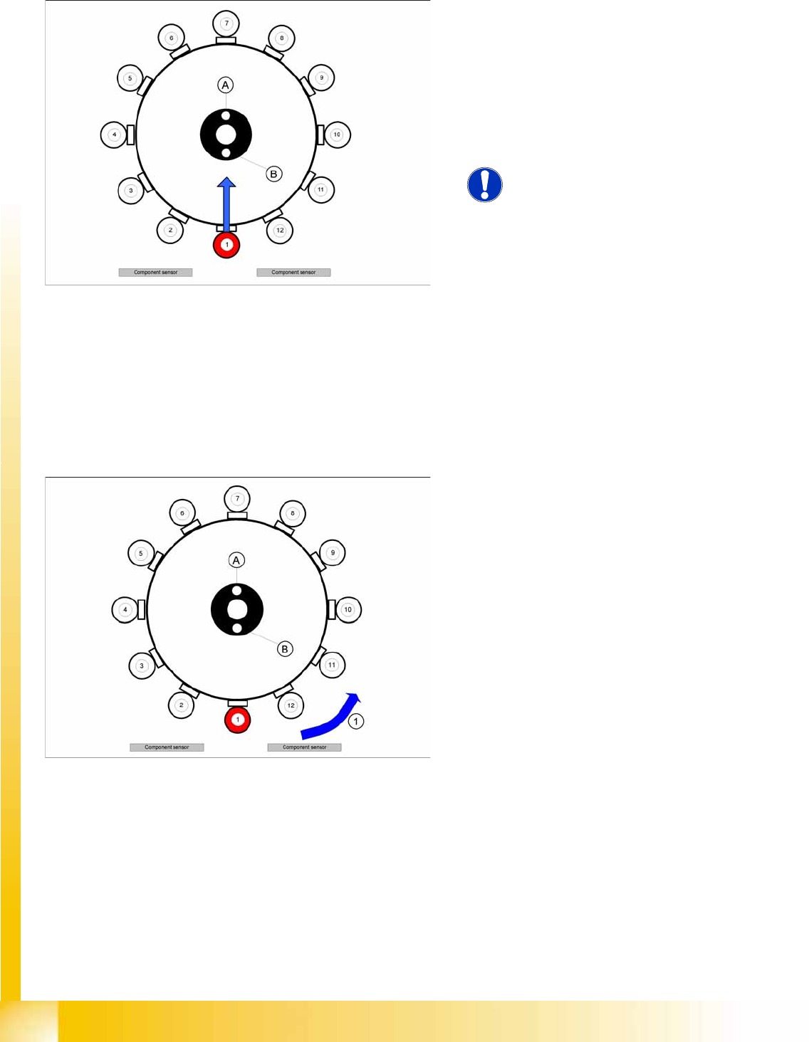
8.3.2 Star Axis Reference Run
8-3: Preparing the Z axis reference run (CPP)
Legend
A : Vacuum measurement hold circuit
B : Vacuum measurement placement circuit
The Z axis return unit ensures that the Z axis is in
a safe position (Z up) as soon as the machine is
started. This is the requirement for starting the Z
axis reference run.
NOTE:
The zero point correction in the Z axis
EEPROM needs to be identical with the
value in the machine data.
From SW 702 this value is
automatically copied to the machine
data when the head is changed.
The Z axis travels down to the zero point pulse of
the incremental encoder. After reaching the zero
pulse, the zero point correction is loaded.
The Z axis travels to the zero point correction
value and the position counter is set to 0 digits.
8-4: Star axis reference run
Legend
1. Direction of rotation
A : Vacuum measurement hold circuit
B : Vacuum measurement placement circuit
The star axis rotates in an anticlockwise direction
(1) to the zero pulse of the incremental encoder.
After reaching the zero pulse, the zero point
correction is loaded. The star axis continues to
rotate around the zero point correction value and
sets the position counter to 0 digits.
Segment number 1 is now in pickup / placement
position.