00196044-05 - sg x und x4i fse_en.pdf - 第322页
Collect, Pick and Place Head (CPP) Reference run CPP head Measuring Z Axis Position fo r Compone nt Recognition by the Component Sensor S tudent Guide (FSE) SI PL ACE X Series and X4I Collect, Pick and Place Head (CPP) E…
Collect, Pick and Place Head (CPP)
Determining the Vacuum and Threshold Values Reference run CPP head
Student Guide (FSE) SIPLACE X Series and X4I
Edition 01/2009 EN Collect, Pick and Place Head (CPP)
321
8.3.5 Determining the Vacuum and Threshold Values
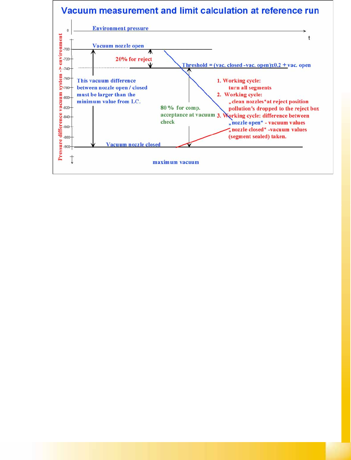
8-6: Measuring and calculating the vacuum values for a reference run
The vacuum is measured twice at the reference point: first with open and then with closed nozzle
tips.
The value with closed valve depends not anymore on the ambient pressure it is controlled by the
pressure control valve. The nozzle fit (nozzle pickup error) and the quality (contamination/damage)
of the nozzle tip influence the vacuum measurement values.
The value by open pressure control valve depends on the nozzle size and condition. The smaller the
nozzle, the greater the open valve value will be. This nozzle-specific value is preset by the SIPLACE
Pro computer. A contaminated or blocked nozzle will also give a higher valve.
The difference between the open and closed nozzles has been preset by the programming system
as an ideal case minimum value. This value is different for all nozzle types e.g. 120 mbar for 1004,
1014 nozzles. If these values are not achieved, the error message "Vakuumdifferenz offen-
geschlossen zu gering" (vacuum difference open-closed is too low) will appear.
The threshold for component acceptance is also set now. Assumed are following values of 660 mbar
In this case we have a value of 660 mbar when the nozzle is open and a value of 852 mbar when
the nozzle is closed. The calculation is performed as follows:
Vacuum distance = (852 (closed) - 660 (open))= 192 mbar
This is greater than the vacuum distance required in the parameter specifications for this nozzle type
(120 mbar). The open vacuum of 660 mbar is significantly greater than the required 250 mbar.
Collect, Pick and Place Head (CPP)
Reference run CPP head Measuring Z Axis Position for Component Recognition by the Component Sensor
Student Guide (FSE) SIPLACE X Series and X4I
Collect, Pick and Place Head (CPP) Edition 01/2009 EN
322
8.3.6 Measuring Z Axis Position for Component Recognition by the Component Sensor
While the Z axis moves downwards, the nozzle interrupts the laser beam of the component sensor. The
axis position is saved and later used for the calculation of the component height and component
presence. At the upwards movement of the Z axis, the laser beam is no longer interrupted and the axis
position is saved again. The component presence can be determined during placement by the
programmed component height (SIPLACE Pro) and the nozzle length, calculated during the height
reference run by the Z axis position counter.
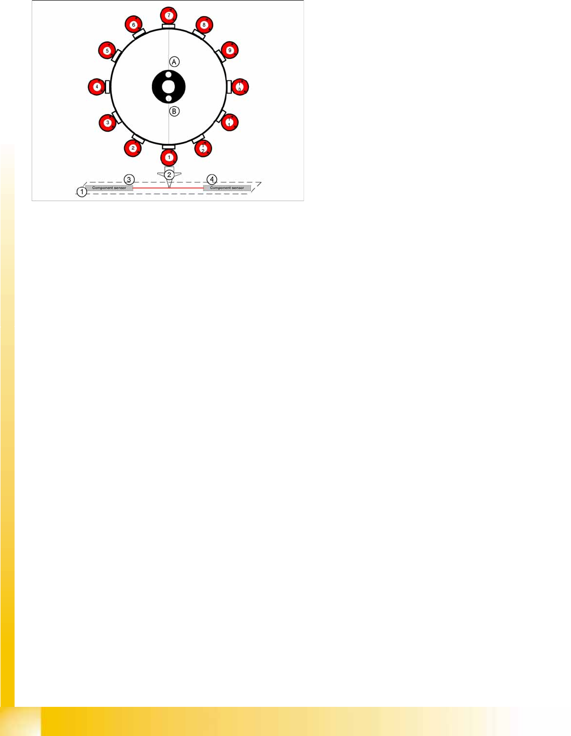
8-7: Nozzle length reference values for component recognition with
component sensor
Legend
1. Component sensor
2. Nozzle
3. IR receiver
4. IR transmitter
During the height reference run, the component
sensor measures the Z axis position for each
segment, to detect the presence/absence of
components in the pickup and placement position.
Collect, Pick and Place Head (CPP)
Working Position on Placement Head Pickup and Placement Cycle for CPP
Student Guide (FSE) SIPLACE X Series and X4I
Edition 01/2009 EN Collect, Pick and Place Head (CPP)
323
8.4 Pickup and Placement Cycle for CPP
8.4.1 Working Position on Placement Head
8.4.2 Placement Modes
The CPP head functions according to the Collect&Place principle, whereby additional operating modes
(Pick&Place and mixed mode) are possible to help extend the component spectrum.
The placement mode is, on the one hand, dependent on the configured camera and, on the other hand,
on the component dimensions and their tolerances in SIPLACE Pro.
The respective placement mode is determined by the Optimizer in SIPLACE Pro band can not be
influenced.
C&P mode: The Collect-and-Place mode is the same mode for the C&P6/12 and C&P20A placement
heads. Components are picked up (the quantity depends on the number of segments), optically centered
with the component camera and then placed.
P&P mode: The Pick-and-Place mode is the mode used for IC and TwinHead. It is therefore also used
for the CPP head, which picks up components with either one or more segments, according to the
component size. Due to their size, it is not possible to rotate these components with the head and they
need to be optically centered via the stationary camera and then placed.
Mixed mode: Mixed mode differentiates between the following two cases:
The components are small enough to be rotated by the head.
The components are too large. Just 2 or 3 components are picked up, centered by the stationary
camera and then placed.
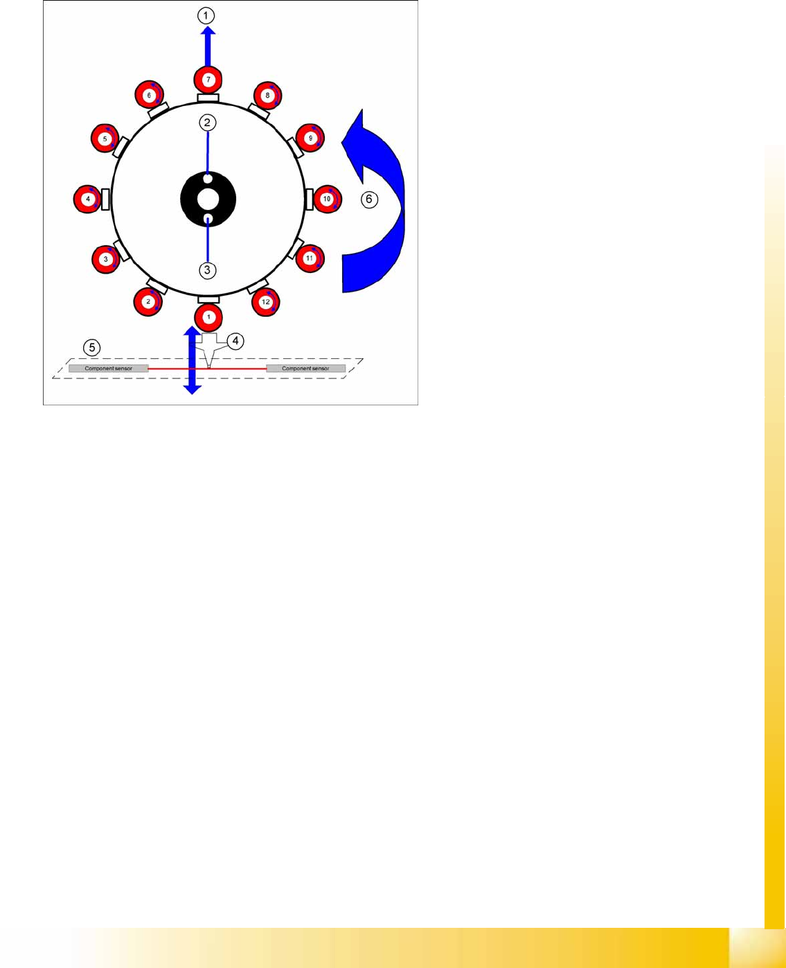
8-8: Working Position on Placement Head
Legend
1. Optical centering (component camera)
2. Vacuum measurement hold circuit
3. Vacuum measurement placement circuit
4. Pickup/placement station and reject position
5. Position of component sensor
6. Direction of processing in C&P mode