00196044-05 - sg x und x4i fse_en.pdf - 第337页
Collect, Pick and Place Head (CPP) Board Descriptions Settings S tudent Guide (FSE) SIPL ACE X Series and X4I Edition 01/2009 EN Collect, Pick and Place Head (CPP) 337 8.5.1.2 Control Module DP drive operation a t positi…
Collect, Pick and Place Head (CPP)
Settings Board Descriptions
Student Guide (FSE) SIPLACE X Series and X4I
Collect, Pick and Place Head (CPP) Edition 01/2009 EN
336
8.5 Settings
8.5.1 Board Descriptions
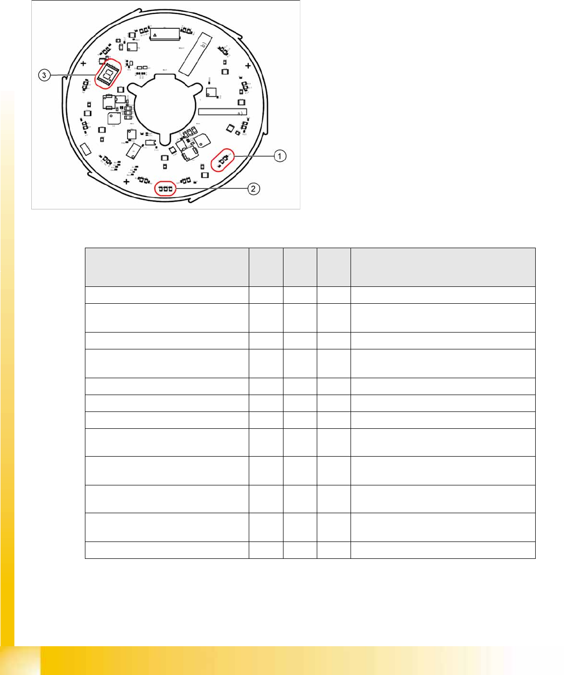
8.5.1.1 Power Module
The 7 segment display (3) provides information about the processor status.
Legend
1. Two LEDs for the status of each DP drive
2. Three LEDs for the operating voltages
3. 7 segment display for the processor status
The status of each DP drive is shown by two LEDs
(green, red) (1).
Three other LEDs (2) show the operating voltages:
Inlet voltage P24 – 24 V
Internal voltage DC/DC converter Vcc – 2.5 V
Internal voltage DC/DC converter Vcc3 – 2.5 V
Status LED
red
LED
green
7
segm
ent
Comment
De energized Off Off 8 LEDs and 7 segment off
Download ZDS (Z down sensor / Z
bottom sensor)
Flash
es
Flash
es
LEDs flash alternatively with high frequency
Download SCS 8 Visualization on 7 segment display
Wait for baud rate recognition
(baud rate not yet recognized)
8 Visualization on 7 segment display
Baud rate recognition error 8 Visualization on 7 segment display
CAN error (error frames) 8 Visualization on 7 segment display
SCS application missing (BIOS active) 8 Visualization on 7 segment display
ZDS application missing (BIOS active) Flash
es
Off Red LED flashes
Error in application 2
e.g. leff error
Off Off Red LED shines permanently
Z down sensor not initialized Flash
es
Off Red LED flashes
DP is referenced but encoder error line
is set
Flash
es
On Red LED flashes / Green LED shines
Z down sensor - no communication Off Off LEDs off
Collect, Pick and Place Head (CPP)
Board Descriptions Settings
Student Guide (FSE) SIPLACE X Series and X4I
Edition 01/2009 EN Collect, Pick and Place Head (CPP)
337
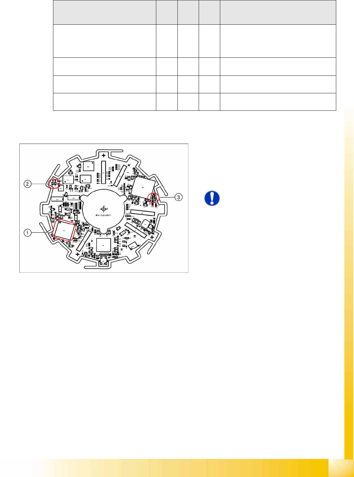
8.5.1.2 Control Module
DP drive operation at positioning Off On If green shines this means that the drive is in
position regulation. LED off means that the
drive has just performed an action (no end
position signal).
ZDS is ready for operation but the drive
has not been referenced
Off Flash
es
Green LED flashes
Open Flash
es
Off Red LED flashes rapidly
Open Off Flash
es
Green LED flashes rapidly
Status LED
red
LED
green
7
segm
ent
Comment
Legend
1. 16 bit processor
2. H1 and H2
3. H3
NOTE:
The status LEDs are not visible, as the
control module is located behind the
power module!
Collect, Pick and Place Head (CPP)
Settings Board Descriptions
Student Guide (FSE) SIPLACE X Series and X4I
Collect, Pick and Place Head (CPP) Edition 01/2009 EN
338
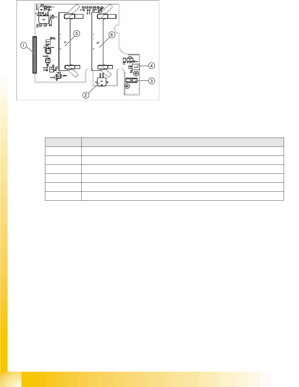
8.5.1.3 Intermediate Distributor 1
LEDs on Intermediate Distributor 1
Legend
Intermediate distributor 1 forms the connection to
intermediate distributor 2 and the adapter board.
The following sensors and actuators are still
connected directly to the CPP head.
1. X25 – connector to intermediate distributor 2
2. X24 – Z motor
3. X22 – connector Z axis encoder (track signals)
with EEPROM
4. X15 – return cylinder
5. X1 – flat ribbon cable connector to head
adapter
6. X2 – flat ribbon cable connector to head
adapter
LED Meaning
V111 Z axis encoder error
V112 Star axis encoder error
V107 Operating voltage + 5V
V106 Operating voltage +15V
V108 Operating voltage -15V
V2 Return cylinder extended