00196044-05 - sg x und x4i fse_en.pdf - 第339页
Collect, Pick and Place Head (CPP) Board Descriptions Settings S tudent Guide (FSE) SIPL ACE X Series and X4I Edition 01/2009 EN Collect, Pick and Place Head (CPP) 339 8.5.1.4 Intermediate Distributor 2 LEDs and Switches…
Collect, Pick and Place Head (CPP)
Settings Board Descriptions
Student Guide (FSE) SIPLACE X Series and X4I
Collect, Pick and Place Head (CPP) Edition 01/2009 EN
338
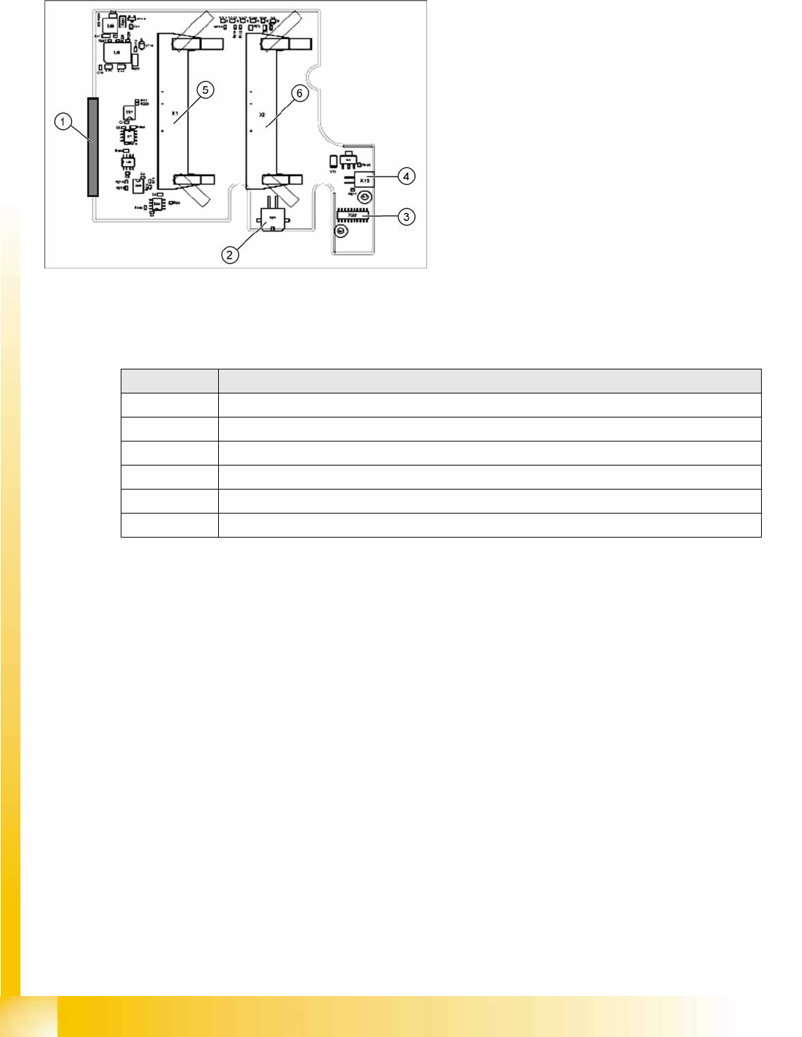
8.5.1.3 Intermediate Distributor 1
LEDs on Intermediate Distributor 1
Legend
Intermediate distributor 1 forms the connection to
intermediate distributor 2 and the adapter board.
The following sensors and actuators are still
connected directly to the CPP head.
1. X25 – connector to intermediate distributor 2
2. X24 – Z motor
3. X22 – connector Z axis encoder (track signals)
with EEPROM
4. X15 – return cylinder
5. X1 – flat ribbon cable connector to head
adapter
6. X2 – flat ribbon cable connector to head
adapter
LED Meaning
V111 Z axis encoder error
V112 Star axis encoder error
V107 Operating voltage + 5V
V106 Operating voltage +15V
V108 Operating voltage -15V
V2 Return cylinder extended
Collect, Pick and Place Head (CPP)
Board Descriptions Settings
Student Guide (FSE) SIPLACE X Series and X4I
Edition 01/2009 EN Collect, Pick and Place Head (CPP)
339
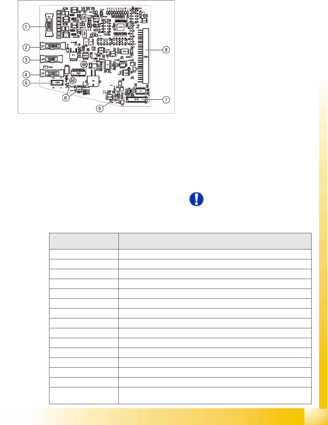
8.5.1.4 Intermediate Distributor 2
LEDs and Switches on Intermediate Distributor 2
Legend
The following sensors and actuators for the CPP
head are connected directly to the intermediate
distributor:
1. X21 – Component sensor
2. X19 – Vacuum sensor holding circuit
3. X29 – Energy transmission barrel collector
ring (24V), (for zero series)
4. X26 – Energy transmission (contact free)
(series status)
5. X20 – Collector ring (E/D transformer for
C&P20A, not used)
6. X23 – Connector star encoder (track signals)
with EEPROM, X25 star motor
7. X12 – Digital pressure control valve
8. X30 – Connector to intermediate distributor 1
9. Switch S1.1: CAN test
switch S1.2: CAN ID
X14, X16, X16B: Test connector CAN bus
X27, X28: Test connector for FPGA
NOTE:
Either X20, X26 or X29 is used!
LED
(from left to right)
Meaning
V106 Z down sensor – „ON“ = Z down sensor enabled
V113 Output FPGA
V112 Output FPGA
V111 Output FPGA
V110 Output FPGA
V109 Output FPGA
V114 Output FPGA
V107 Output FPGA
V108 Output FPGA
V11 „ON“ pressure control valve not ready (5V status)
V14 Operating voltage DP axes 24V
V17 Potential display – „ON“ = voltage present
V18 Potential display – „ON“ = voltage present
Switch S1.1 CAN test – switch over to a cable for head CAN bus
Switch S1.2 CAN ID – setting to a fixed CAN ID for the pressure control valve (for test purposes
only)
Collect, Pick and Place Head (CPP)
Nozzle Changer (NC) Board Descriptions
Student Guide (FSE) SIPLACE X Series and X4I
Collect, Pick and Place Head (CPP) Edition 01/2009 EN
340
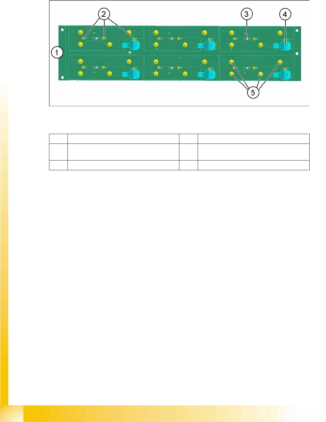
8.6 Nozzle Changer (NC)
8-16: Nozzle changer for X machine
Legend
In X series machines, a maximum of twelve nozzle changers are possible for each location,
depending on the machine configuration.
The nozzle changer for the X machines has been extended to include the following functions:
– Magazine ID
– Height query
The nozzle changer carrier can accommodate the various magazine types for the C&P20A and CPP
heads.
The machine recognizes the configured magazines via the magazine query (microswitch).
If the wrong magazines are configured for the head, a warning will be issued to prevent a head crash.
– 10xx magazine: Switch 2 (center) pressed
– 20xx magazine: Switches 1 and 3 pressed
– 28xx magazine: Switches 1, 2 and 3 pressed
(1) Nozzle changer carrier (2) Microswitch 1, 2 and 3 for magazine query
(3) Actuator for opening and closing the NC
magazine
(4) Unlocking lever for NC magazine
(5) Fixture clips for NC magazines