00196044-05 - sg x und x4i fse_en.pdf - 第344页
Collect, Pick and Place Head (CPP) Vacuum System Nozzle types S tudent Guide (FSE) SI PL ACE X Series and X4I Collect, Pick and Place Head (CPP) Edition 01/2 009 EN 344 8.7 V acuum System Legend (1) Compressed air distri…
Collect, Pick and Place Head (CPP)
Nozzle types Nozzle Changer (NC)
Student Guide (FSE) SIPLACE X Series and X4I
Edition 01/2009 EN Collect, Pick and Place Head (CPP)
343
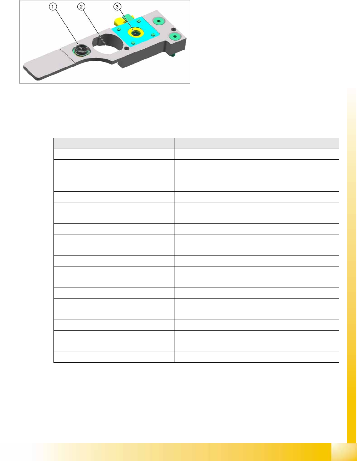
Nozzle Station X4I for CPP Head
8.6.3 Nozzle types
The wide component spectrum available for the CPP head means that two different nozzle series are
needed: 20xx and 28xx.
Legend
1. Take off for 20xx nozzles
2. Take off for 28xx nozzles
3. Reject station for CPP nozzles
Nozzle type Component types Comments
2003 0402
2004 0603, 0805, 1206
2005 01005
2006 0201
2007 0402, 0603
2014 0603, 0805, 1206
2020 PLCC Height: Smaller than 0.75 mm
2021 PLCC Height: Smaller than 4.75 mm
2032 Mini meif, diodes
2033 1206, tantal
2034 Maxi melf, diodes
2035 Tantal C, SO
2036 Mini melf, diodes
2037 SO
2038 Al. Kond.
2039 Al. Kond.
2057 Calibration nozzle
2817 SOX Height: Larger than 0.75 mm, smaller than 4.5 mm
2820 PLCC
2821 PLCC Height: Larger than 4.25 mm, smaller than 8.25 mm
Collect, Pick and Place Head (CPP)
Vacuum System Nozzle types
Student Guide (FSE) SIPLACE X Series and X4I
Collect, Pick and Place Head (CPP) Edition 01/2009 EN
344
8.7 Vacuum System
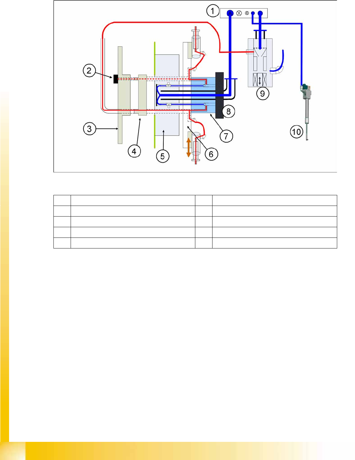
Legend
(1) Compressed air distributor (2) Holding circuit sensor
(3) Rear cover – CPP head (4) Smooth distributor disc
(5) Valve terminal (6) Star carrier with DP drives
(7) Hold circuit (8) Silencer
(9) Pressure control valve (digital) (10) Z axis return cylinder
Collect, Pick and Place Head (CPP)
Vacuum System Function Vacuum System
Student Guide (FSE) SIPLACE X Series and X4I
Edition 01/2009 EN Collect, Pick and Place Head (CPP)
345
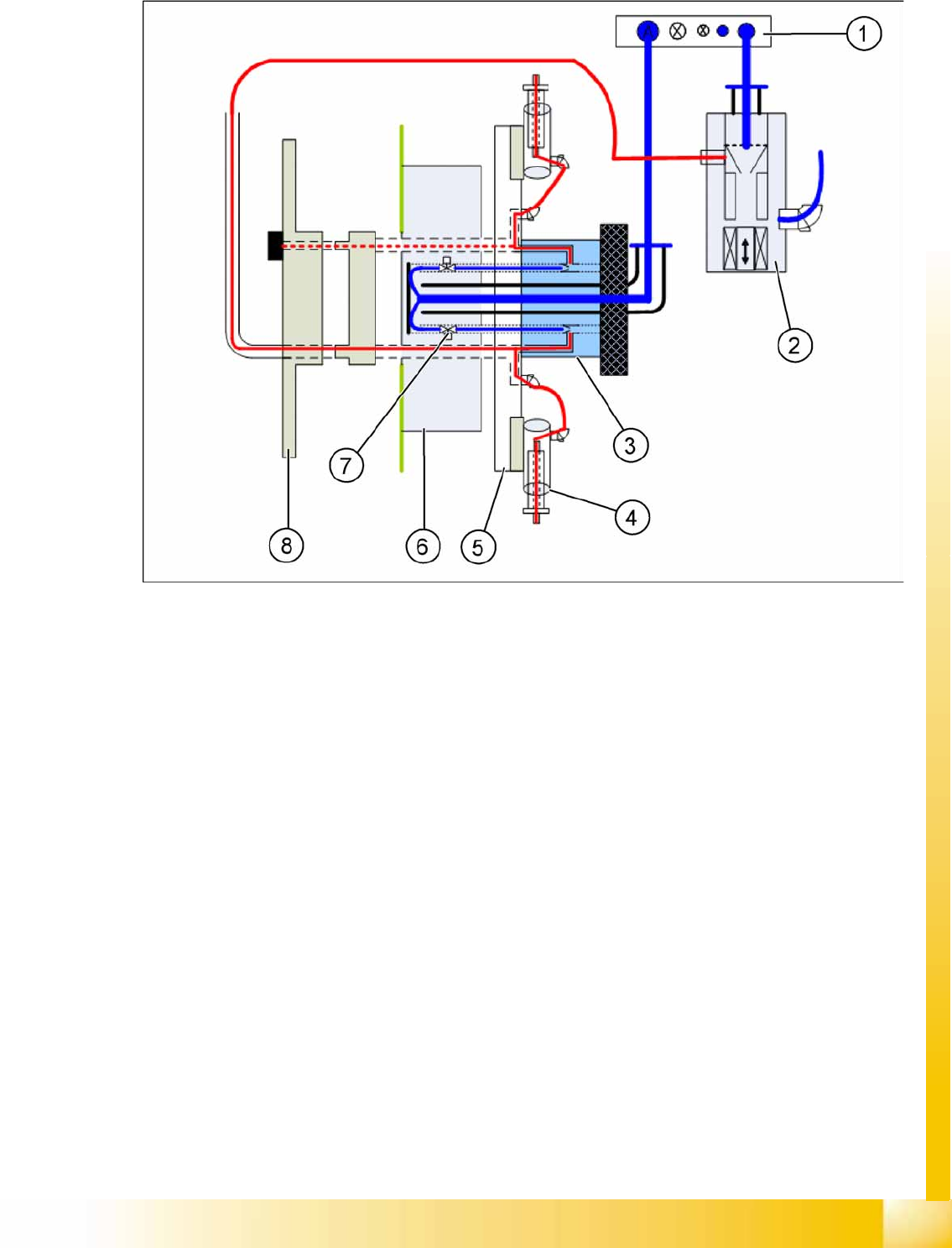
8.7.1 Vacuum System Function
The pneumatic distributor (1) supplies the pressure control valve (2), the holding circuit (3) and the
return cylinder with 4.5 bar compressed air.
The compressed air is fed directly through the holding circuit (3) to the valve terminal (6). There it is
distributed into 12 channels.
Each channel in the holding circuit can be separately opened or closed with a valve (7).
The compressed air is fed from the valve terminal to the holding circuit, through the 12 channels. The
vacuum for the holding circuit of all 12 segments is generated there via 12 venturi nozzles.
The vacuum is fed from the holding circuit via the star carrier (5) to the nozzle segment (4).
The holding circuit sensor is located in the CPP head cover (8). The holding circuit sensor can be
used to measure the vacuum of any segment which is in the 12.00 position.