00196044-05 - sg x und x4i fse_en.pdf - 第349页
Twin Head Technical Data Twin H ead Overview S tudent Guide (FSE) SIPL ACE X Series and X4I Edition 01/2009 EN T win Head 349 9 T win Head 9.1 Overview 9.1.1 T echnical Dat a T win Head Legend 1. Module 1 2. Module 2, ro…

Collect, Pick and Place Head (CPP)
Room for Your Sketches and Notes Placing Components
Student Guide (FSE) SIPLACE X Series and X4I
Collect, Pick and Place Head (CPP) Edition 01/2009 EN
348
Twin Head
Technical Data Twin Head Overview
Student Guide (FSE) SIPLACE X Series and X4I
Edition 01/2009 EN Twin Head
349
9 Twin Head
9.1 Overview
9.1.1 Technical Data Twin Head
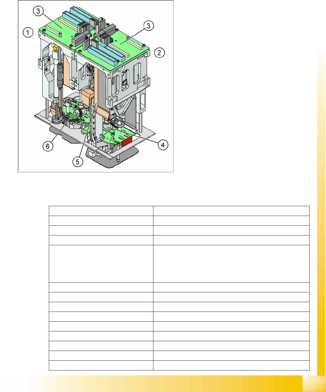
Legend
1. Module 1
2. Module 2, rotate by 180 ° compared to module
1.
3. Main board on modul 1 and modul 2
4. D Axis
5. Linear motorZ Axis
6. Z axis incremental measurement system
The Twin head consists of two identical modules
which work according to the Pick&Place principle.
The second P&P head is rotated 180 degrees.
For the Twin-head, new nozzles (Type 5xx) were
developed. However, the nozzles of the
Pick&Place head type 4xx and the nozzles of the
Collect&Place heads type 8xx and 9xx we can use
with an adapter.
Placement accuracy (X/Y) 35µm by 4 sigma with IC camera
Placement accuracy (X/Y) 30µm by 4 sigma with FC camera
Placement accuracy (Angle) 0,07° by 4sigma
Placement speed 3500 cph
Maximum component size: 50 up to 40 mm single measurement on both segments
69 up to 10 mm (multiple measurement on both segments)
125 up to 10 mm ( multiple measurement on one segment)
200 up to 125 mm (multiple measurement with restrictions on one
segment )
Max. component height 25 mm
Placement force 1 - 15 N
D-Axis / Resolution direct drive / 0,001 degree
Z Axis / Resolution Linear motor / 0,5 µm
Travel range Z axis app. 60 mm
Nozzle types 5xx (4xx, 8xx, 9xx with adapter)
Distance between the segments approx. 71,00 mm
Max. weight of component 100 g
Option high force Twin head placement force max. 30 N (only X series)
Twin Head
Overview TWIN Head Assemblies
Student Guide (FSE) SIPLACE X Series and X4I
Twin Head Edition 01/2009 EN
350
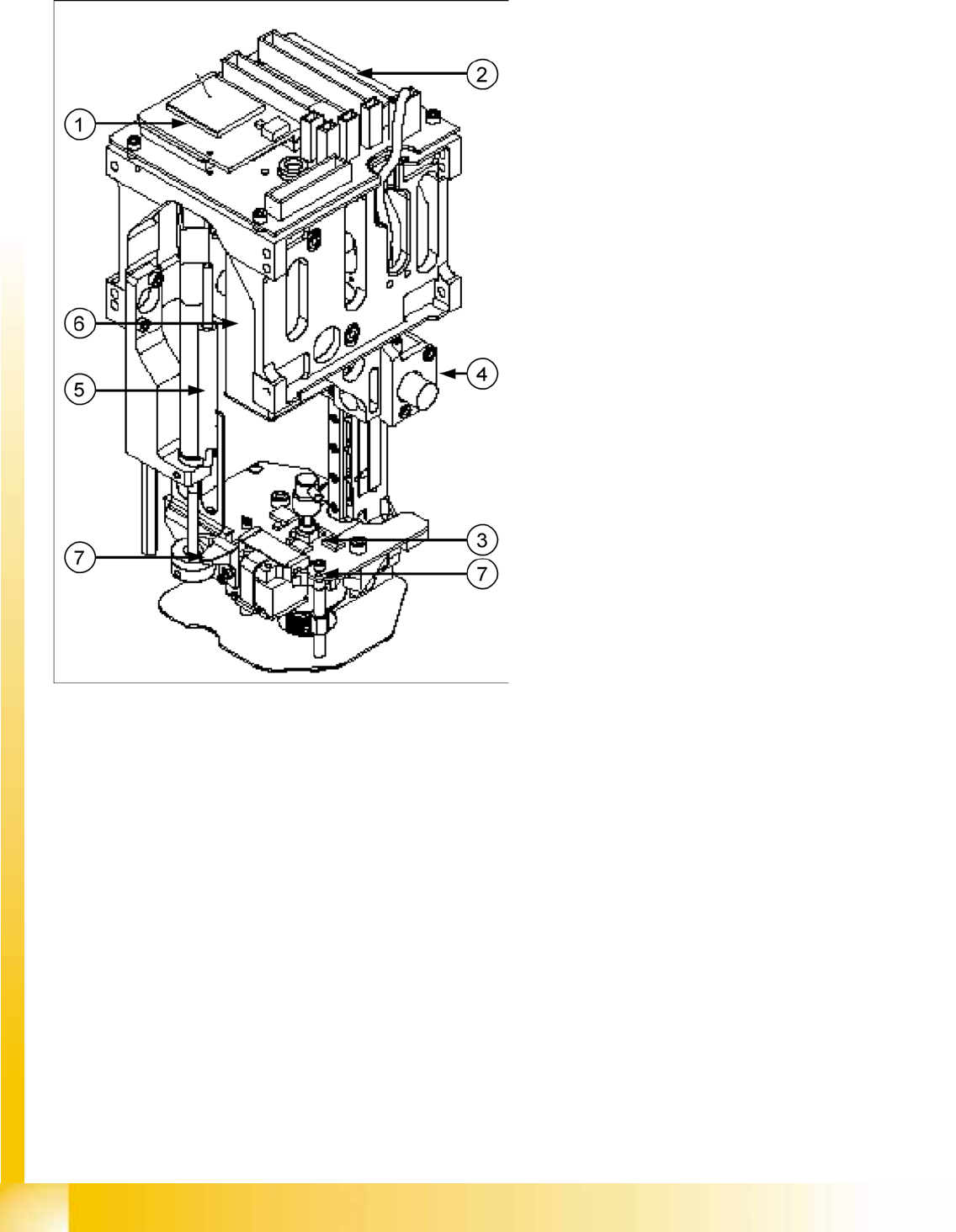
9.1.2 TWIN Head Assemblies
9-1: TWIN Head Assemblies
Legend
1. CAN Bus processor board (not mounted, is
now on the head interface C500)
2. Twin head head board
3. D-axis complete with incremental encoder and
force sensor
4. Incremental encoder Z axis
5. Return unit to return the Z axis in a safety area
in case of power fail
6. Vacuum generator
7. Actuator for return unit (right) / screw on the
force measurement board (left)