00196044-05 - sg x und x4i fse_en.pdf - 第351页
Twin Head TWIN Head Assemblies Overview S tudent Guide (FSE) SIPL ACE X Series and X4I Edition 01/2009 EN T win Head 351 9.1.2.1 V acuum generator T win- Head 9-2: Vacuum generator The vacuum generator automatica lly con…
Twin Head
Overview TWIN Head Assemblies
Student Guide (FSE) SIPLACE X Series and X4I
Twin Head Edition 01/2009 EN
350
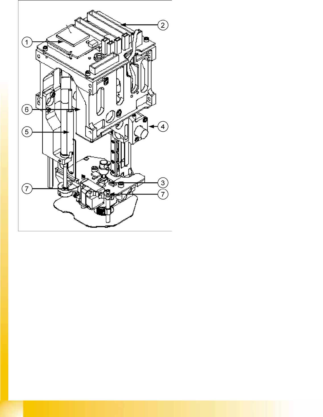
9.1.2 TWIN Head Assemblies
9-1: TWIN Head Assemblies
Legend
1. CAN Bus processor board (not mounted, is
now on the head interface C500)
2. Twin head head board
3. D-axis complete with incremental encoder and
force sensor
4. Incremental encoder Z axis
5. Return unit to return the Z axis in a safety area
in case of power fail
6. Vacuum generator
7. Actuator for return unit (right) / screw on the
force measurement board (left)
Twin Head
TWIN Head Assemblies Overview
Student Guide (FSE) SIPLACE X Series and X4I
Edition 01/2009 EN Twin Head
351
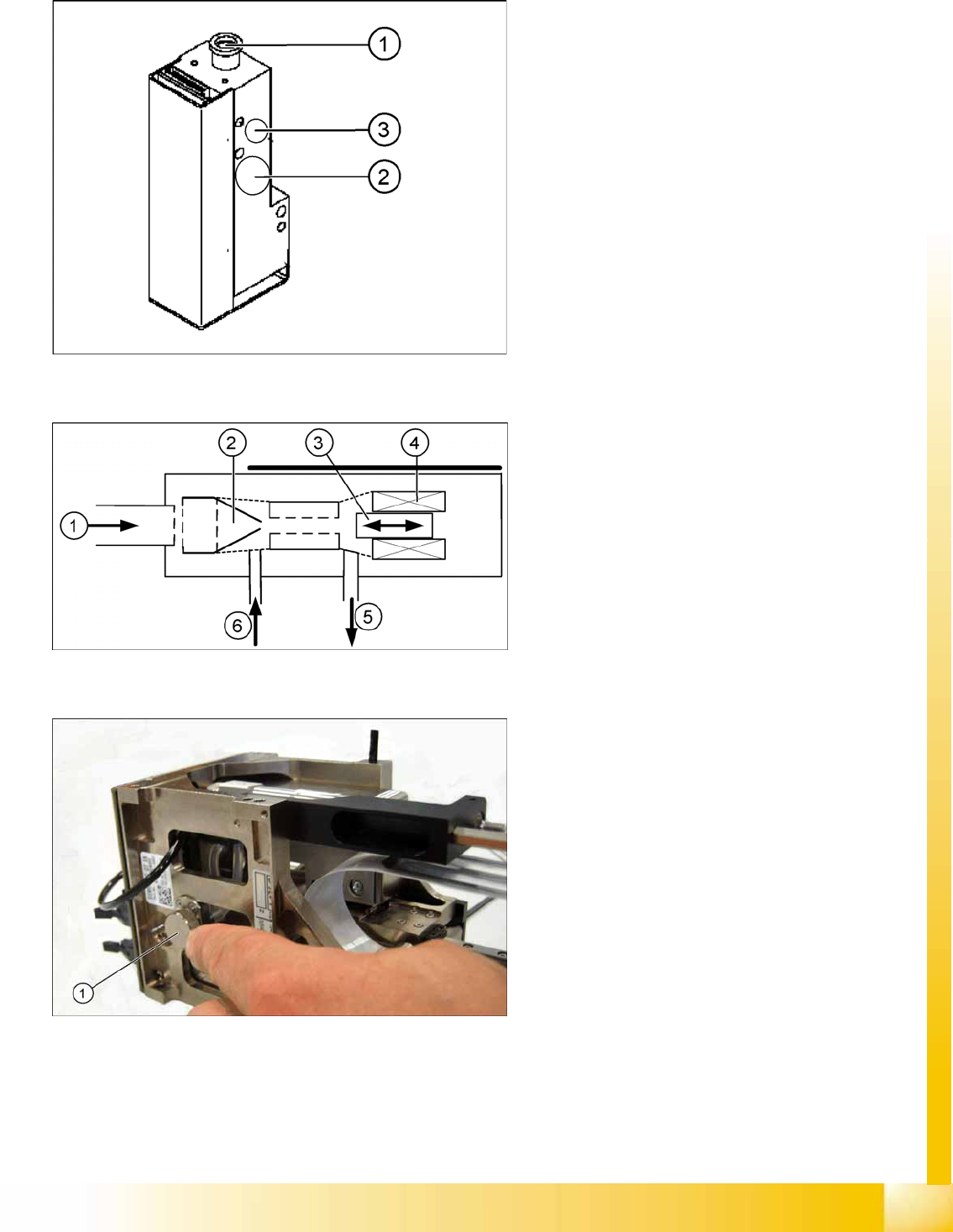
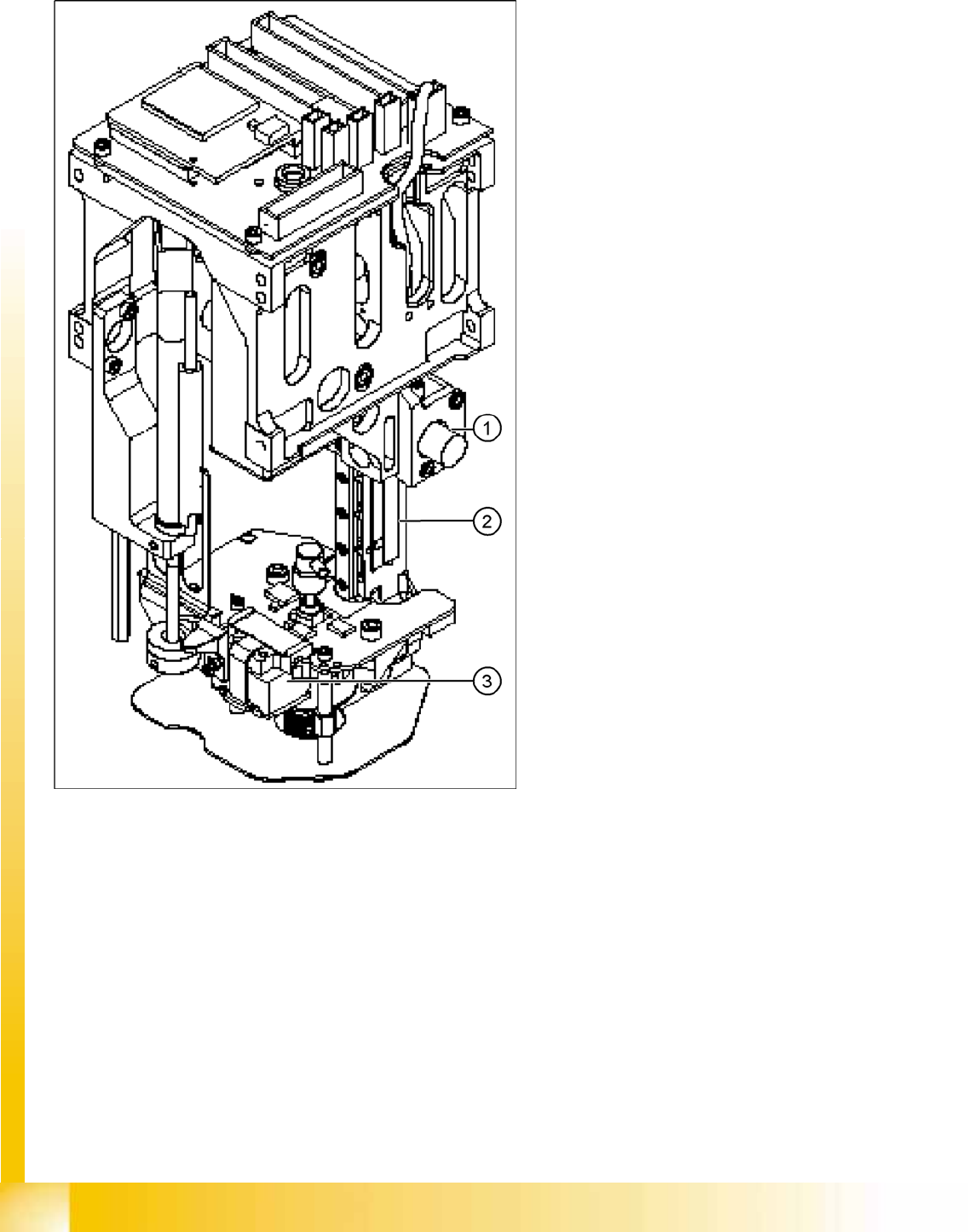
9.1.2.1 Vacuum generator Twin- Head
9-2: Vacuum generator
The vacuum generator automatically controls the
vacuum, air blast and the zero balancing position
(middle position-->no vacuum and no air blast) for
the segments, with the aid of an iron core and
inductor.
Legend
1. Compressed air input
2. X series, D3: Cooling for X linear motor
D1: Discharged air to silencer
3. Output vacuum - vacuum is passed through
the D-axis motor shaft and then to the nozzle.
9-3: Principle of the vacuum generator
Legend
1. Compressed air input
2. Venturi nozzle
3. Plunger (iron core)
4. Plunger drive (inductor)
5. Discharged air to silencer
6. Vacuum air blast output
9-4: Filter for the vacuum system (example of Twin segment version 03
shown)
Legend
1. Filter for the vacuum system on the Twin-
head.
The Filter is mounted on the return unit and used
as an attenuator to control the vacuum. The filter
with the additional volume reduces the oscillation
of the vacuum generator and guarantees an
accurate vacuum and air blast supply. The filter is
serviced at regular intervals, which must be
adhered to (see maintenance guide).
Twin Head
Reference Run TWIN Head Assemblies
Student Guide (FSE) SIPLACE X Series and X4I
Twin Head Edition 01/2009 EN
352
9.2 Reference Run
9-5: Twin-head Z,D- axes
The Twin-head consist of two segments which
have 2 axes Z and D and the X and Y axes at the
Gantry.
Before you start the reference run the return
cylinder move out to the lower home position. On
both modules the vacuum is on, until the vacuum
generator is initialized.
Legend
1. Z axis incremental encoder
2. Z axis linear incremental scale
3. D-axis incremental encoder with incremental
glass scale