00196044-05 - sg x und x4i fse_en.pdf - 第352页
Twin Head Reference Run TWIN Head Assemblies S tudent Guide (FSE) SI PL ACE X Series and X4I T win Head Edition 01/2009 EN 352 9.2 Reference Run 9-5: Twin-head Z,D- axes The Twin-head consist of two segments which have 2…
Twin Head
TWIN Head Assemblies Overview
Student Guide (FSE) SIPLACE X Series and X4I
Edition 01/2009 EN Twin Head
351
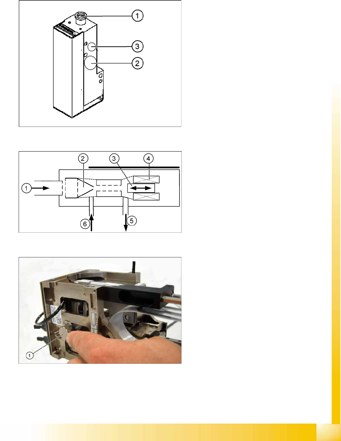
9.1.2.1 Vacuum generator Twin- Head
9-2: Vacuum generator
The vacuum generator automatically controls the
vacuum, air blast and the zero balancing position
(middle position-->no vacuum and no air blast) for
the segments, with the aid of an iron core and
inductor.
Legend
1. Compressed air input
2. X series, D3: Cooling for X linear motor
D1: Discharged air to silencer
3. Output vacuum - vacuum is passed through
the D-axis motor shaft and then to the nozzle.
9-3: Principle of the vacuum generator
Legend
1. Compressed air input
2. Venturi nozzle
3. Plunger (iron core)
4. Plunger drive (inductor)
5. Discharged air to silencer
6. Vacuum air blast output
9-4: Filter for the vacuum system (example of Twin segment version 03
shown)
Legend
1. Filter for the vacuum system on the Twin-
head.
The Filter is mounted on the return unit and used
as an attenuator to control the vacuum. The filter
with the additional volume reduces the oscillation
of the vacuum generator and guarantees an
accurate vacuum and air blast supply. The filter is
serviced at regular intervals, which must be
adhered to (see maintenance guide).
Twin Head
Reference Run TWIN Head Assemblies
Student Guide (FSE) SIPLACE X Series and X4I
Twin Head Edition 01/2009 EN
352
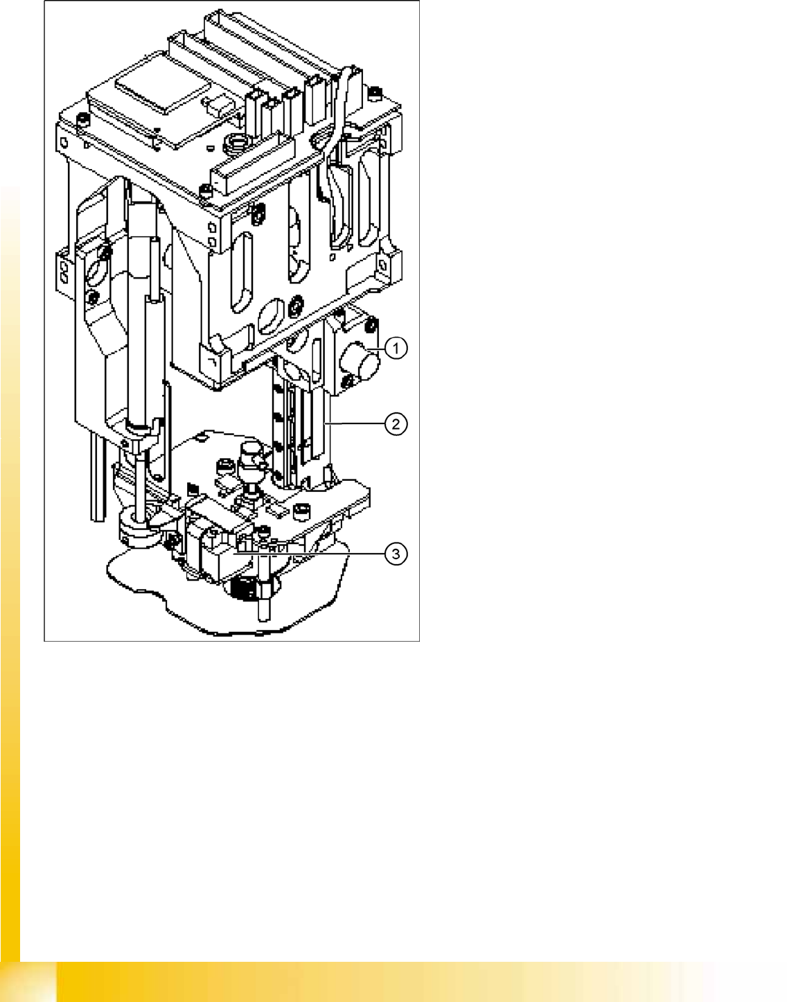
9.2 Reference Run
9-5: Twin-head Z,D- axes
The Twin-head consist of two segments which
have 2 axes Z and D and the X and Y axes at the
Gantry.
Before you start the reference run the return
cylinder move out to the lower home position. On
both modules the vacuum is on, until the vacuum
generator is initialized.
Legend
1. Z axis incremental encoder
2. Z axis linear incremental scale
3. D-axis incremental encoder with incremental
glass scale
Twin Head
Reference run at Z axis Reference Run
Student Guide (FSE) SIPLACE X Series and X4I
Edition 01/2009 EN Twin Head
353
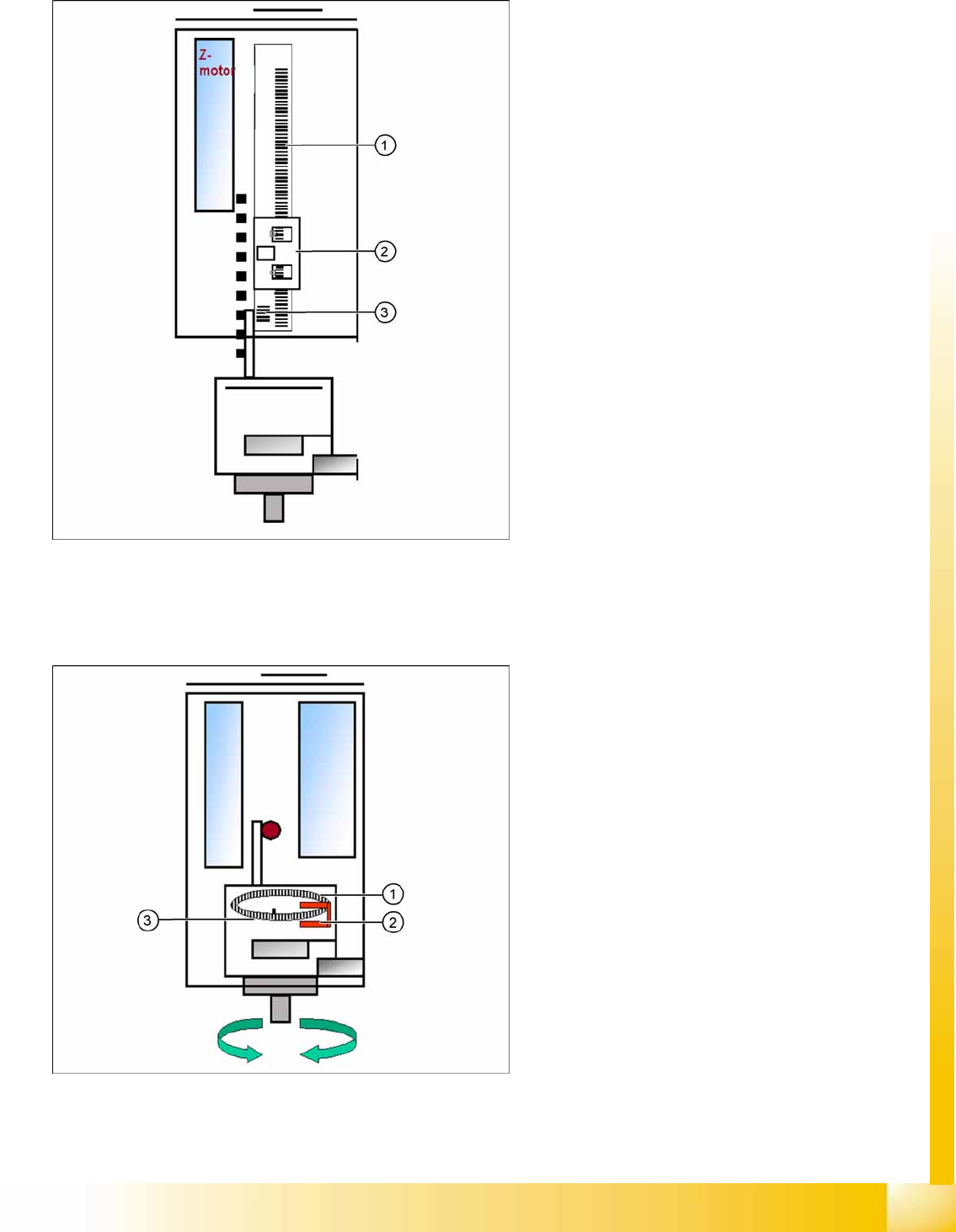
9.2.1 Reference run at Z axis
9.2.2 Reference run at D- axis
9-6: Reference run Z axis
Legend
1. Incremental scale mounted on moveable part
of the Z Axis
2. Fixed Incremental encoder
3. Zero puls on the incrementale scale (only one
for Z axis)
Z Axis search for the commutation point of the
linear motors (in a special mode because of
the danger of a movement downwards). (A 3
phase motor continues to run at the correct
time and in the correct sequence, when the
current is switched from 1 phase to the next
one.)
Then the Z Axis move upwards to the Zero
pulse and load the zero point correction.
The zero point correction, max. and min. travel
range, are determined when you calibrate the
head height.
9-7: Reference run D-axis
Legend
1. Incremental glass scale D-axis
2. Incremental encoder
3. Zero pulse on the incremental glass scale
Then the D-axis (turning axis) executes the
reference run.
The D-axis runs to the zero pulse of the D- axis
encoder. The zero point correction value will be
loaded. The D-axis moves to the reference
position, in accordance with the prefix shown
before the value.
Reference run completed! This is followed by
the gantry reference run (see Section Gantry).