00196044-05 - sg x und x4i fse_en.pdf - 第355页
Twin Head General Twin Head Pickup and Place Cycle S tudent Guide (FSE) SIPL ACE X Series and X4I Edition 01/2009 EN T win Head 355 9.3 T win Head Pickup and Place Cycle 9.3.1 General 9.3.2 T win Head Placement Principle…
Twin Head
Reference Run Vacuum check
Student Guide (FSE) SIPLACE X Series and X4I
Twin Head Edition 01/2009 EN
354
9.2.3 Vacuum check
After the CAN bus processor for the vacuum/air blast distributor has booted, the vacuum/air blast
distributor is initialized. This means that vacuum/air blast generator is adjusted to ensure that neither
vacuum or air blast is generated at the nozzle.
The Gantry axes move the Twin-head to the reject position.
Over the reject box the Vacuum-, air blast generator switch to air blast to reject components and
check the air blast.
The vacuum/air blast generator now switches over to vacuum and the open vacuum at both
segments (X and D3 machine, D1: one Twin segment) is measured*.
After measurement, the pressure is adjusted back to 0 bar.
The vacuum reference run has now been completed for the Twin head.
* The closed vacuum value for the Twin segments relates to the calibration value which was determined
in SITEST.
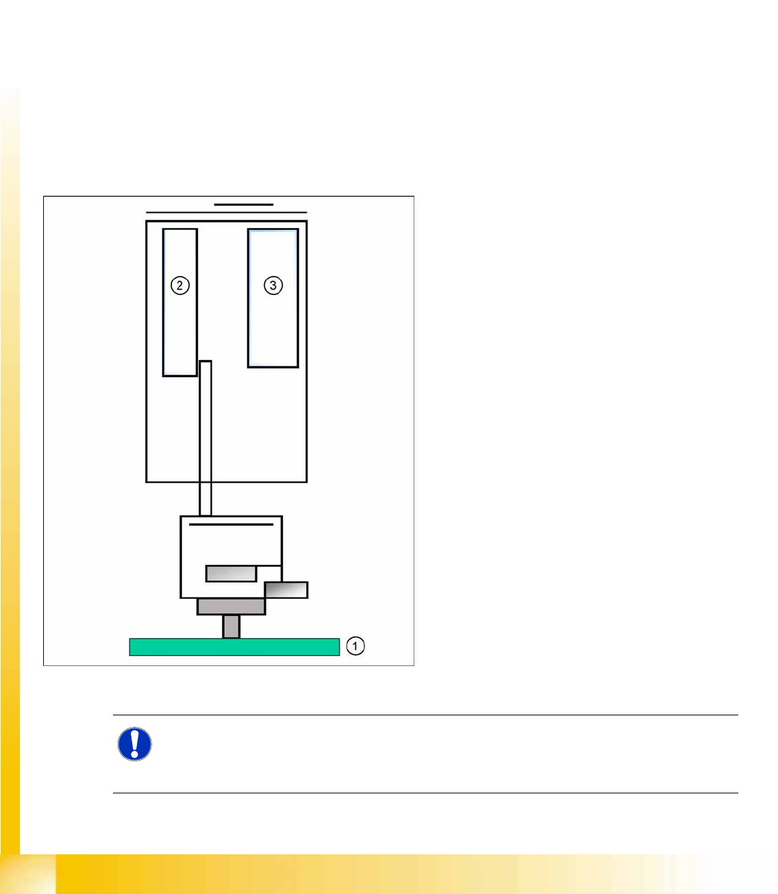
9.2.4 Height Reference Run
9-8: Measure nozzle height
With this function we check the correct nozzle type
which is programmed. The nozzle length is taken
to calculate the pick up and placement height for
the following placements.
Legend
1. Top of fixed conveyor side
2. Z motor
3. Vacuum - air blast distribution
X The gantry moves the placement heads above
the fixed conveyor side.
X The Z axis positions module 2 (X/D3 machine)
downwards.
X The travel range of the Z axis is taken to
calculate the Twin head height in relation to
the nozzle type.
X Now the same happen with module 1.
X The maximum length tolerance is 0,4 mm: If
the length difference is too high an error
message is displayed.
NOTE:
Both modules are measured at the same position of the PCB conveyor!
This Twin head reference run is performed parallel to the C&P head reference run in the other
placement area.
Twin Head
General Twin Head Pickup and Place Cycle
Student Guide (FSE) SIPLACE X Series and X4I
Edition 01/2009 EN Twin Head
355
9.3 Twin Head Pickup and Place Cycle
9.3.1 General
9.3.2 Twin Head Placement Principle
During the PCB transport time, the gantry waits at the theoretical fiducial position, to perform board
centering (and inkspot recognition) after PCB clamping. With the " Whispering down the machine"
option, gantry 3 only evaluates 2 fiducials.
Than the Twin-head start to collect one component with module 1 and one component with module 2.
These components are then centered with the IC camera (FC camera) and are placed.
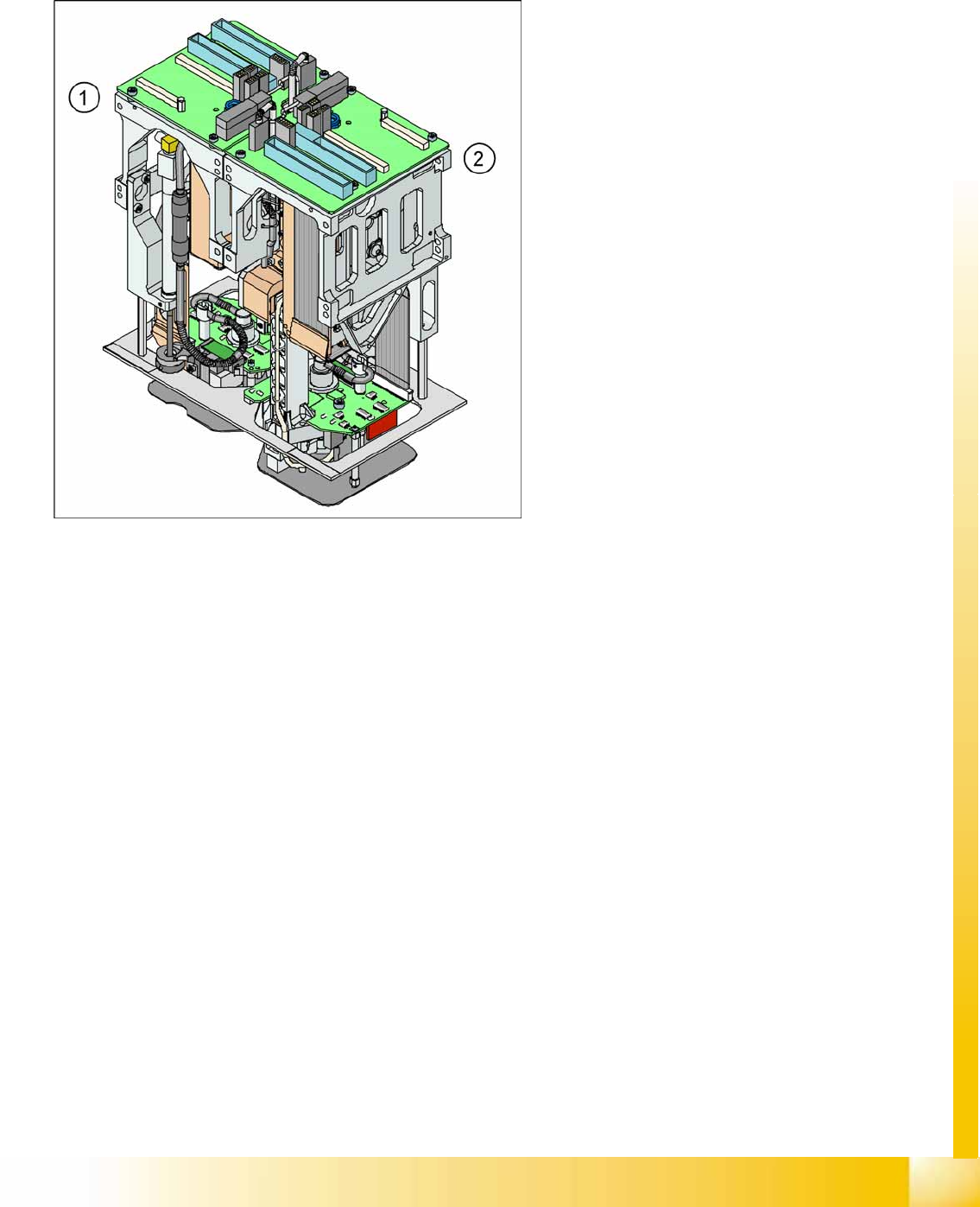
9-9: View of Twin head
The TWIN Head module 2 (2) has been mounted
at an angle of 180 degrees to module 1 (1).
The distance between the nozzles is
approximately 71 mm in X - direction.
The maximum component height is 25 mm.
The contact force at placement can be
programmed between 0.5 N and 15 N (up to
30 N for a highforce Twin head).
The rotational accuracy is 0.07 degrees,
4 sigma/X and Y axes 35 µm 4 sigma.
The placement of special shaped components
has been improved:
– Components up to 200x125mm, weight of
100g
– Placement performance: 3700 cph for
large components
Twin Head
Twin Head Pickup and Place Cycle Preparations for Component Pickup (Module 1)
Student Guide (FSE) SIPLACE X Series and X4I
Twin Head Edition 01/2009 EN
356
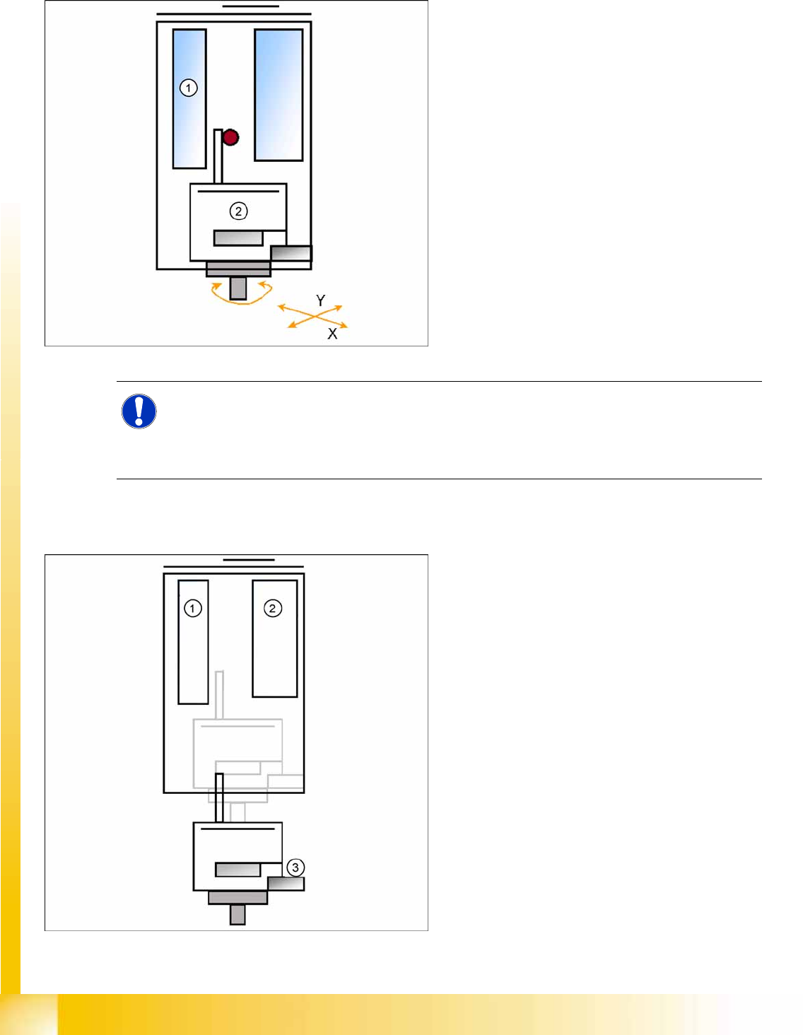
9.3.3 Preparations for Component Pickup (Module 1)
9.3.3.1 Picking up the Component (Module 1)
Legend
1. Z motor
2. D motor
PCB-position recognition and Ink dot
recognition.
The X and Y gantry axes move to the feeder
track or pickup position.
Start D Axis to set the Pick up angle during X /
Y positioning.
Communication to component trolley ‘Feeder
ready’ opens feeder pickup window.
NOTE:
For greater accuracy, the first five components of each board are centered above the IC camera
at 0° and 180° (SW 504). With the SW 505 we will check the offset between nozzle and IC/ FC
camera via a fiducial near the IC/FC camera after a defined time of 3 min. The fiducial is on a
metal plate and this plate is fixed between the camera and machine frame.
Legend
1. Z motor
2. Vacuum/air blast generator
3. Force sensor
Z Axis position downwards with Standard Pick
up mode at 2 N Pick up force.
At contact with the component the force
increase up to the programmed value.
When this value is reached, the end signal is
triggered and the vacuum check is activated.