00196044-05 - sg x und x4i fse_en.pdf - 第360页
Twin Head Twin Head Pickup and Place Cycle Preparati ons for Placement (Module 2 Component) S tudent Guide (FSE) SI PL ACE X Series and X4I T win Head Edition 01/2009 EN 360 9.3.6.1 Placement (Module 1 Component) 9.3.7 P…
Twin Head
Component centering module 1 and 2 Twin Head Pickup and Place Cycle
Student Guide (FSE) SIPLACE X Series and X4I
Edition 01/2009 EN Twin Head
359
9.3.5 Component centering module 1 and 2
9.3.6 Preparations for Placement (Module 1 Component)
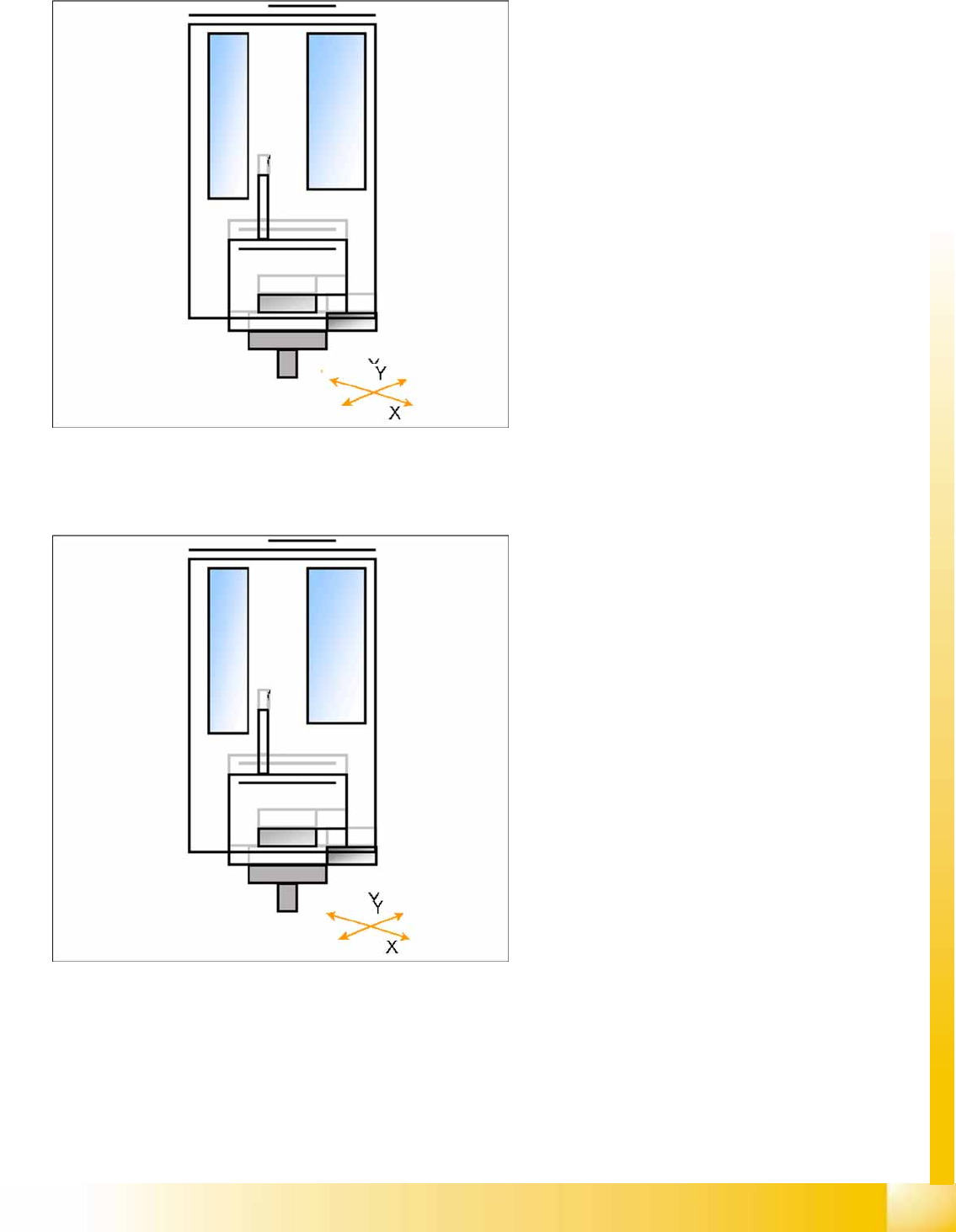
X/Y axes position module 1 via the IC camera.
Start Z Axis to move Bottom side of comp. to
focus level.
‘flash’ IC-camera illumination
Move Z Axis again upwards.
centering 1st component (near placement
angle) is finished
The X/Y axes position module 2 over the IC
camera.
Start Z Axis to move Bottom side of comp. to
focus level.
‘flash’ IC-camera illumination
Move Z Axis again upwards.
The X/Y gantry axes move to the corrected
placement position.
The D-axis rotates by the placement angle
correction value.
Twin Head
Twin Head Pickup and Place Cycle Preparations for Placement (Module 2 Component)
Student Guide (FSE) SIPLACE X Series and X4I
Twin Head Edition 01/2009 EN
360
9.3.6.1 Placement (Module 1 Component)
9.3.7 Preparations for Placement (Module 2 Component)
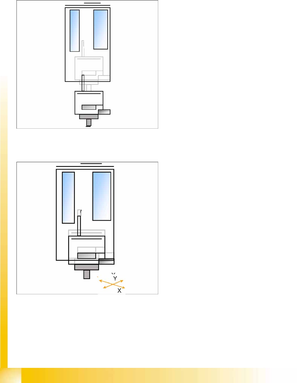
The Z axis moves downwards in standard
mode (2 N contact force).
The Force increase up to the programmed
level after contact of the component on the
PCB.
With this Force signal the End signal is set.
The air blast control is activated too.
At air blast level for placement ..
The next placement sequence is prepared for
a module 2 component.
The X/Y gantry axes moves to the actual
(corrected) placement position.
The D-axis rotates by the placement angle
correction value.
Twin Head
Preparations for Placement (Module 2 Component) Twin Head Pickup and Place Cycle
Student Guide (FSE) SIPLACE X Series and X4I
Edition 01/2009 EN Twin Head
361
9.3.7.1 Placing the Component (Module 2 Component)
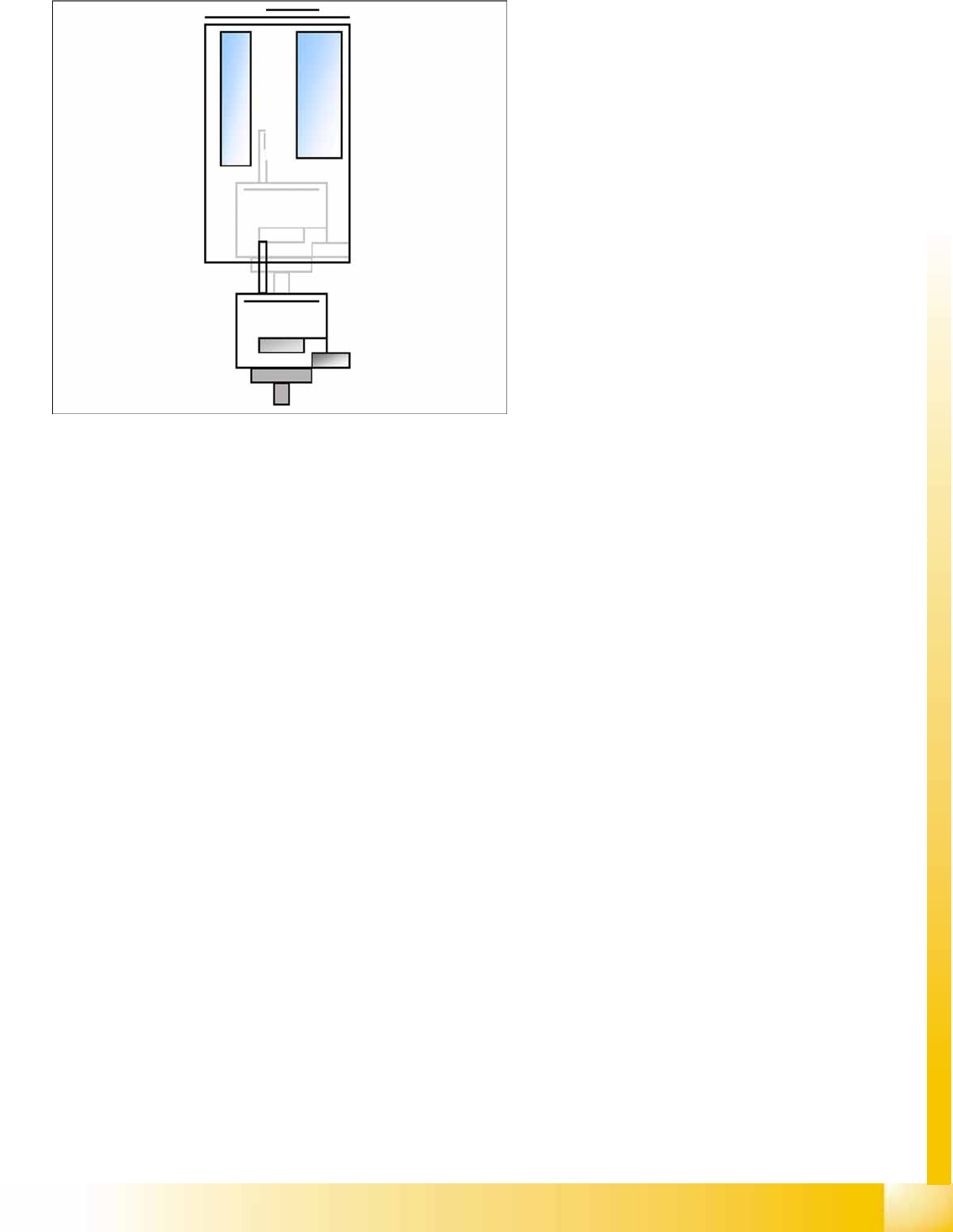
The Z axis moves downwards in standard
mode (2 N contact force).
The Force increase up to the programmed
level after contact of the component on the
PCB.
With this Force signal the End signal is set.
The air blast control is activated too.
At air blast level for placement Z Axis move
upwards with Standard profile.
The next pickup sequence is prepared for
module 1.
* Troubleshooting: If the air blast pressure is not
reached during placement, a vacuum check will be
performed in the Z axis up position, to see whether
the component has been placed or not.