00196044-05 - sg x und x4i fse_en.pdf - 第366页
Twin Head Settings Parameter and Calibrations S tudent Guide (FSE) SI PL ACE X Series and X4I T win Head Edition 01/2009 EN 366 9.4.2 Parameter and Calibrations 9.4.2.1 Overview of Calibration Step s and Para meters in S…
Twin Head
Description of Boards on the Twin Head Settings
Student Guide (FSE) SIPLACE X Series and X4I
Edition 01/2009 EN Twin Head
365
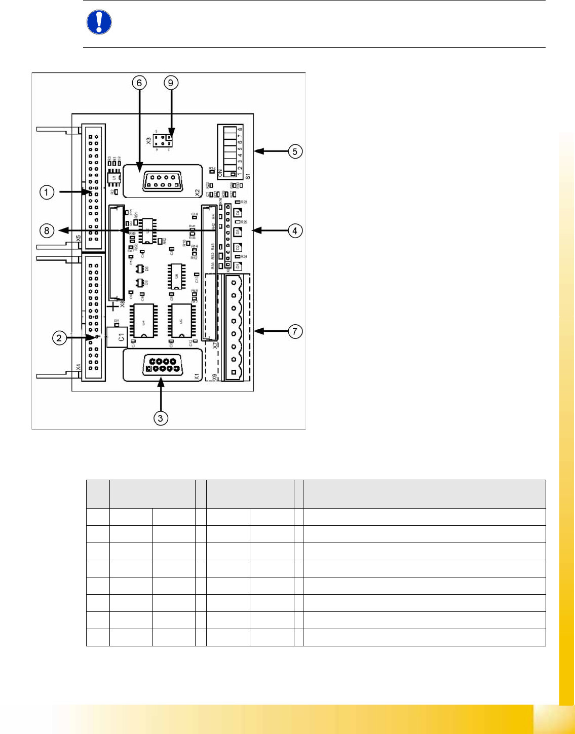
9.4.1.3 Vision Control Board for IC Camera or FC Camera
The vision control board is installed in sector 2 and sector 4 for the stationary cameras.
to 5) DIP switch
NOTE:
When using stationary camera ≧ version 04, the Vision control board is integrated into the
cameras. The Vision control board no longer applies in the sectors.
9-12: Vision control board IC camera
Legend
1. Connector for FC camera illumination
2. Connector for stationary IC camera
illumination
3. Service connector
4. LEDs (downwards D4 - D1)
+5 V/-15 V/+15 V/+40 V
5. DIP switch
6. Connector CAN Bus
7. Voltage supply for Vision control
Connector for DC/DC converter (sector 2)
DC/DC distributor (sector 4)
8. Connectors for 16 bit CAN Bus processor
(TQM modules)
9. Flash signal (not used for Siplace Vision)
S Sector 2
Main distributor
Sector 4
Subdistributor
Description
1OFF OFF CAN terminal resistor - 120 Ohm not set
2OFF OFF RESET
3OFF OFF Bootstrap
4OFF OFF TEST
5OFF ON P1 address switch, gantry ID 1
6ON ONP0 address switch, gantry ID 2
7OFF OFF CAN - ID 1
8OFF OFF CAN -ID 0
Twin Head
Settings Parameter and Calibrations
Student Guide (FSE) SIPLACE X Series and X4I
Twin Head Edition 01/2009 EN
366
9.4.2 Parameter and Calibrations
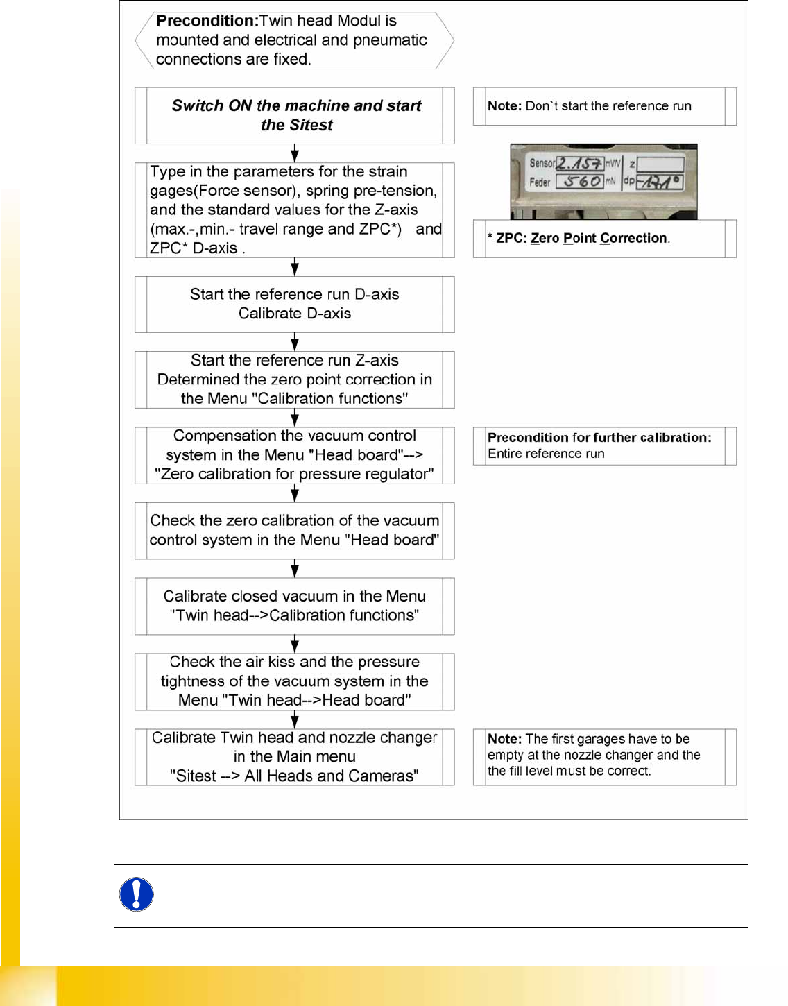
9.4.2.1 Overview of Calibration Steps and Parameters in SITEST
9-13: Overview calibration steps and parameter
NOTE:
This steps are necessary during initial setup or a replacement of the module. The detail
description are explained on the following pages.
Twin Head
Twin Head Parameters Settings
Student Guide (FSE) SIPLACE X Series and X4I
Edition 01/2009 EN Twin Head
367
9.4.3 Twin Head Parameters
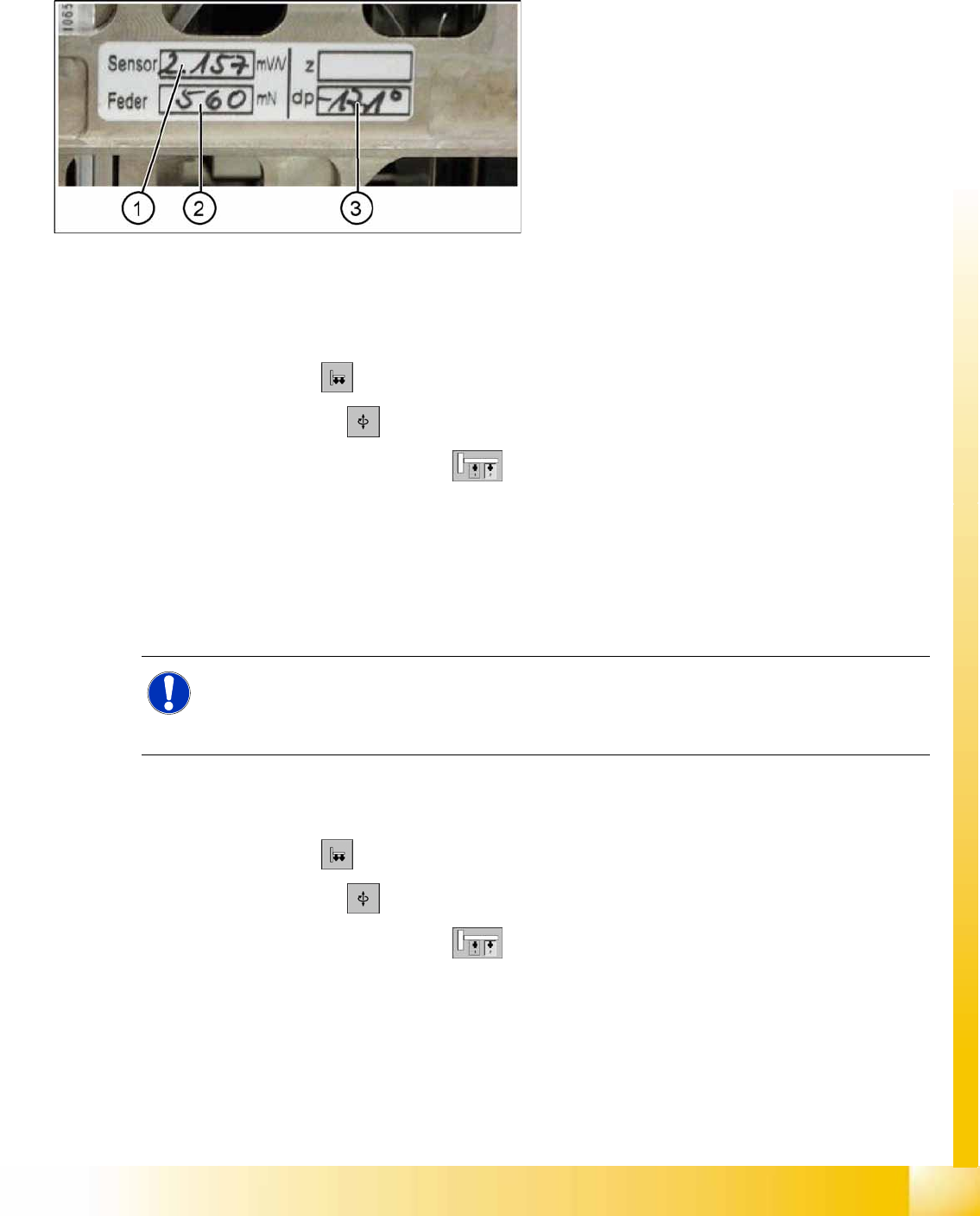
Each module has a label with correction parameters which need to be enetered in SITEST at initial setup
or when the P&P module is replaced.
Parameter force sensor and spring pre-tension
SITEST:
X Select
Twin Head
X Select
Axis functions
X Select the appropriate Twin module.
X Select the checkbox
Z axis
.
X Select the
Parameter...
menu and enter the values
Force sensor comparative value
in [mV/V]. This value is always smaller than 3.0 [mV/V].
and
Spring pretension
in [mN]. This value is between 300 and 700 [mN]).
If these values are not entered in SITEST as specified on the Twin segment, this will result in inaccurate
calculation of the placement force (1 to 15N).
Zero point correction (ZPC) D-axis
SITEST:
X Select
Twin Head
X Select
Axis functions
X Select the appropriate Twin module.
X Select the checkbox
D Axis
X Select
Positions...
X Disable the checkbox
digits
X Specify the relevant ZPC value in 1/100 degrees in line 2. "ZPC from the Label" and select
Accept
.
9-14: Label with D axis correction value and parameters for the TWIN
module.
Legend
1. Sensor (parameters for DMS strips)
2. Spring (spring pre-tension)
3. DP (zero point correction D-axis)
NOTE:
The adjusting screw (fine thread) for the spring pre-tension MUST NOT be adjusted! It is
currently not possible to measure the spring pretension at the customer site, meaning that the
placement head needs to be exchanged.