00196044-05 - sg x und x4i fse_en.pdf - 第367页
Twin Head Twin Head Parameters Settings S tudent Guide (FSE) SIPL ACE X Series and X4I Edition 01/2009 EN T win Head 367 9.4.3 T win Head Parameters Each module has a label w ith correction parameters wh ich need to be e…
Twin Head
Settings Parameter and Calibrations
Student Guide (FSE) SIPLACE X Series and X4I
Twin Head Edition 01/2009 EN
366
9.4.2 Parameter and Calibrations
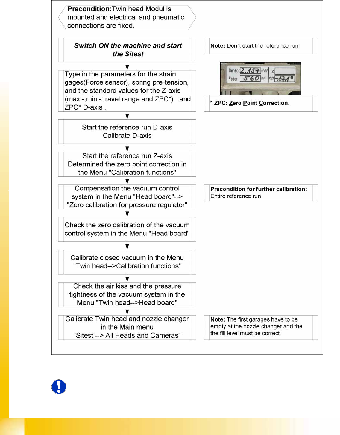
9.4.2.1 Overview of Calibration Steps and Parameters in SITEST
9-13: Overview calibration steps and parameter
NOTE:
This steps are necessary during initial setup or a replacement of the module. The detail
description are explained on the following pages.
Twin Head
Twin Head Parameters Settings
Student Guide (FSE) SIPLACE X Series and X4I
Edition 01/2009 EN Twin Head
367
9.4.3 Twin Head Parameters
Each module has a label with correction parameters which need to be enetered in SITEST at initial setup
or when the P&P module is replaced.
Parameter force sensor and spring pre-tension
SITEST:
X Select
Twin Head
X Select
Axis functions
X Select the appropriate Twin module.
X Select the checkbox
Z axis
.
X Select the
Parameter...
menu and enter the values
Force sensor comparative value
in [mV/V]. This value is always smaller than 3.0 [mV/V].
and
Spring pretension
in [mN]. This value is between 300 and 700 [mN]).
If these values are not entered in SITEST as specified on the Twin segment, this will result in inaccurate
calculation of the placement force (1 to 15N).
Zero point correction (ZPC) D-axis
SITEST:
X Select
Twin Head
X Select
Axis functions
X Select the appropriate Twin module.
X Select the checkbox
D Axis
X Select
Positions...
X Disable the checkbox
digits
X Specify the relevant ZPC value in 1/100 degrees in line 2. "ZPC from the Label" and select
Accept
.
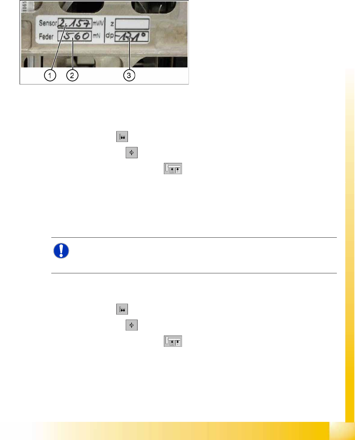
9-14: Label with D axis correction value and parameters for the TWIN
module.
Legend
1. Sensor (parameters for DMS strips)
2. Spring (spring pre-tension)
3. DP (zero point correction D-axis)
NOTE:
The adjusting screw (fine thread) for the spring pre-tension MUST NOT be adjusted! It is
currently not possible to measure the spring pretension at the customer site, meaning that the
placement head needs to be exchanged.
Twin Head
Settings Twin Head Parameters
Student Guide (FSE) SIPLACE X Series and X4I
Twin Head Edition 01/2009 EN
368
X Perform a reference run for the D-axis.
X Do not forget to perform D axis calibration afterwards. (calibration device [03008862-xx])
Zero point correction (ZPC) Z axis
SITEST:
X Select
Twin Head
X Select
Axis functions
X Select the appropriate Twin module , enable
Z axis
X Select
Positions...
and enter the following values:
(Deactivate ’display in digit’ button)
Maximum position: 57500 µm
Minimum position: -2000 µm
Zero point correction: 0 µm
X ==> Perform a head height calibration (ZPC for the Z axis).
X Calibrate the head height of the Twin module.
NOTE:
With the SW 505 The D axis value applies for Twin modules 1 and 2, if the NPC is entered in
line 2 at Positions. The staiton automatically calcualtes the ZPC for Twin module 1 (ZPC Twin
module 2 + 180° = ZPC for Twin module 1) .
Example for the value shown on the label above:
-17100 (module 2) or
-900 (module 1)
NOTE:
Enter the standard values for the Z axis, only if the reference run or the calibration head height
not successfully.
NOTE:
Make sure that the 517 nozzle is on the Twin head.
NOTE:
The zero point correction, max. and min. travel range of the Z axis are determined when you
calibrate the head height.