00196044-05 - sg x und x4i fse_en.pdf - 第370页
Twin Head Settings Calibrating the Head Height S tudent Guide (FSE) SI PL ACE X Series and X4I T win Head Edition 01/2009 EN 370 9.4.4.1 Manual Calculation of the D- Axis Zero Point Correction SITEST: X Select Twin Head …
Twin Head
Calibrating the D-Axis Settings
Student Guide (FSE) SIPLACE X Series and X4I
Edition 01/2009 EN Twin Head
369
9.4.4 Calibrating the D-Axis
X Place the calibration nozzle for the Twin head by hand on the sleeve of the appropriate P&P module.
Make sure that the two adjust pins of the nozzle fit correctly.
X Perform an axis reference run for the D-axis.
X Now check the alignment of the nozzle:
The drilling on the calibration nozzle must point to the center (SW 505 or higher) of the machine (for
SR/MC 504.0x to machine outside) and the nozzle must be aligned parallel to the PCB conveyor.
X Assign the nozzle "516" for the P&P module to be calibrated:
SITEST:
X Select
Twin Head
X Select the nozzle changer head function.
X Select the appropriate "segment" from the list.
X Select
Edit
==> mark "516" and select
Accept
.
X Enable
Select Segment
.
X Select
Confirm Exchange
.
SITEST:
X Select
Twin Head
X Select
Calibration functions
X Select the appropriate Twin module
X Open the
Calibrate zero point D axis
menu.
X When requested to do so by the SW, connect the D-axis calibration nozzle.
The ZPC will be automatically determined through the angle recognition of the nozzle outline.
Repeat this procedure until the new value does not deviate more than +/- 0.01° from the previous
value.
See also:
J
9.4.4.1 Manual Calculation of the D-Axis Zero Point Correction [
J
370]
NOTE:
The exact zero point correction (ZPC) of the D axis is calibrated automatically on the SIPLACE
HF/HF3 by means of a calibration nozzle.
Correct calibration can only be expected if the ZPC angle differs less than +/- 5 degrees from
the real value.
NOTE:
If the calibration is not successful, you can roughly determine the zero point correction manually
and enter this value. (see Section (9.4.4.1 Manual Calculation of the D-Axis Zero Point Correc-
tion
J
370 ) )
Twin Head
Settings Calibrating the Head Height
Student Guide (FSE) SIPLACE X Series and X4I
Twin Head Edition 01/2009 EN
370
9.4.4.1 Manual Calculation of the D-Axis Zero Point Correction
SITEST:
X Select
Twin Head
X Select
Axis functions
X Select the appropriate Twin module.
X Select the checkbox
D Axis
X Select
Positions...
X Set the zero point correction to
0
.
X Perform an axis reference run for the D-axis.
X Put the calibration nozzle for the Twin head manually on the sleeve of the appropriate Twin module.
Make sure that the two adjust pins of the nozzle fit correctly.
X Deactivate the D axis of the Twin module at the axis board.
X Manually rotate the nozzle into the zero position:
The drilling on the calibration nozzle must point to the center (from SW 505 onwards) of the machine
and the nozzle must be aligned parallel to the PCB conveyor.
X In order to display the position of the D axis, open the
Z axis
menu by checking the checkbox and
then return to
D Axis
.
X Enter the shown value for the D-axis as zero point correction value.
X Activate the D axis at the axis board.
X Perform an axis reference run for the D-axis.
X Now check the position of the nozzle:
The drilling on the calibration nozzle must point to the center (from SW 505 onwards) of the machine
and the nozzle must be aligned parallel to the PCB conveyor.
X Do not forget to perform D axis calibration afterwards. (see Section (9.4.4 Calibrating the D-Axis
J
369 ) ).
9.4.5 Calibrating the Head Height
The Z axis zero point correction is determined with this menu.
SITEST:
X Select
Twin Head
X Select
Calibration functions
X Select
Calibrate head height
.
NOTE:
Make sure that the 517 nozzle is on the Twin head and has been entered in the software.
The zero point correction, plus the maximum and minimum travel range for the Z axis will be
correctly set after performing "head height" calibration.
Twin Head
Calibration of Vacuum Generator on the Twin Head Settings
Student Guide (FSE) SIPLACE X Series and X4I
Edition 01/2009 EN Twin Head
371
9.4.6 Calibration of Vacuum Generator on the Twin Head
The vacuum generator is part of a Twin head segment and creates the vacuum and air blast for the
pickup and placement process. The zero calibration of the vacuum generator should be performed on
initial setup at the customer site and after exchanging the vacuum generator or Twin module.
If the vacuum generator is not calibrated, incorrect threshold values will be taken to calculate the open
and closed vacuum and you could get error messages such as "No component on the nozzle or nozzle
is dirty".
With the aid of the zero calibration, we can position the vacuum generator motor in a middle or neutral
position, so that there is no air blast or vacuum present at the nozzle.
9.4.6.1 Zero Calibration of Vacuum Generator
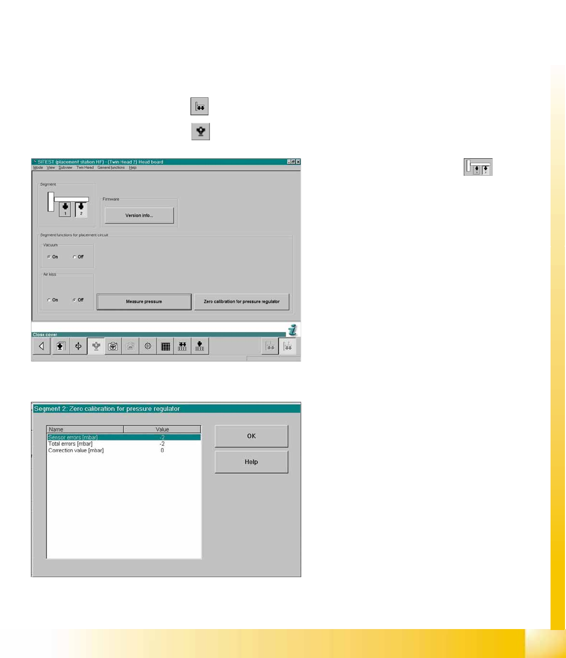
X Start the SITEST.
SITEST:
X Select
TWIN Head
X Select
Head Board
9-15: SITEST functions - head board
X Select the required
Segment
X Close the nozzle of the appropriate Twin
module (e.g. by sealing it with your finger tip).
9-16: Correction values after zero calibration
X Select
Zero calibration pressure regulator
The dialog box on the left shows the correction
value calculated.
X Select
OK
.
The correction value will be accepted - now the
reference value equals the ambient pressure.