00196044-05 - sg x und x4i fse_en.pdf - 第376页
Twin Head Nozzle changer Position and assembly the nozzle changer S tudent Guide (FSE) SI PL ACE X Series and X4I T win Head Edition 01/2009 EN 376 9.5 Nozzle changer 9.5.1 Position and assembly the nozzle changer 9.5.1.…
Twin Head
Manual Lowering of Z Axis Settings
Student Guide (FSE) SIPLACE X Series and X4I
Edition 01/2009 EN Twin Head
375
Since both segments of the Twin head are fitted at an angle of 180°, there are two different methods for
moving the Z axis downwards.
CAUTION:
When manually lowering the Z axis, the Twin head module can be easily damaged!
X Manual lowering may only be performed by trained personnel!
ATTENTION:
Before performing manual lowering of the Z axis, make sure the Z axis has been released at the
relevant axis controller board.
X When releasing the Z axis, the Z axis return cylinder moves upwards.
X If the axis is not released, the return cylinder will automatically move upwards when the Z axis
is manually lowered, which could cause injuries and damage to the placement head.
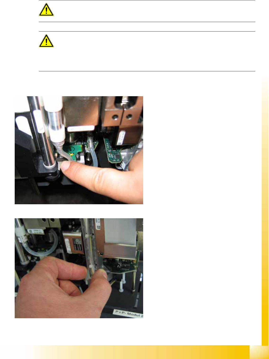
Lowering the Z Axis at P&P Module 1
To safely press the Z axis downwards, apply
manual pressure to the marked part of the return
unit driver.
Lowering the Z Axis at P&P Module 2
The Z axis can be moved downwards at segment
2 by taking hold of the carrier arm from both sides
and then pushing this down.
Twin Head
Nozzle changer Position and assembly the nozzle changer
Student Guide (FSE) SIPLACE X Series and X4I
Twin Head Edition 01/2009 EN
376
9.5 Nozzle changer
9.5.1 Position and assembly the nozzle changer
9.5.1.1 Position
9.5.1.2 Nozzle Changer Position at Location with an MTC
SW 603 allows you to install an MTC in a placement area with 2 gantries. However, you need a special
adapter for the Twin head NC, if using this configuration.
9.5.1.3 Fitting the Nozzle Changer Magazine
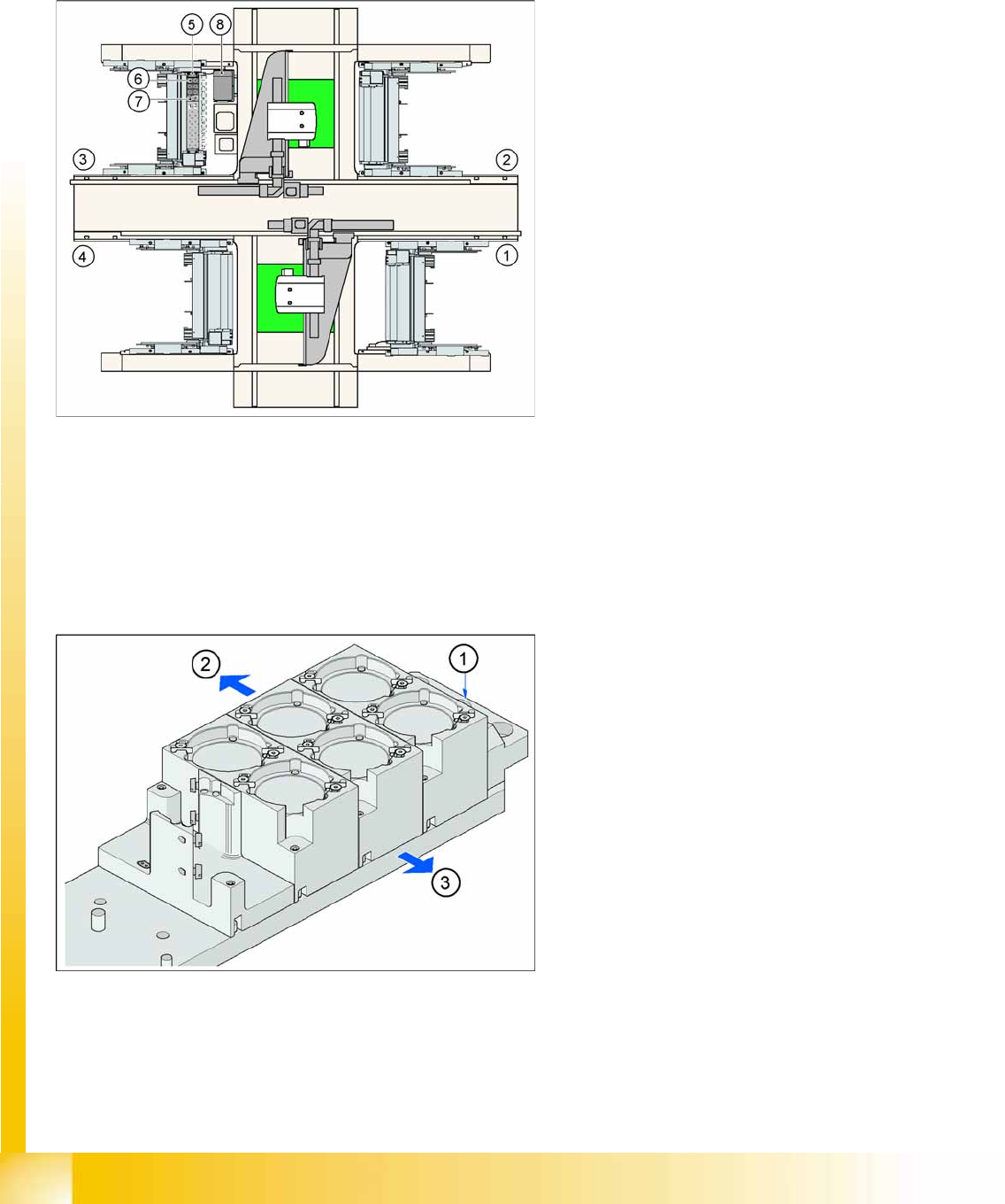
9-18: Position of "standard nozzle changer" – sector 3 shown here
Legend
1. Feeder area 1
2. Feeder area 2
3. Feeder area 3
4. Feeder area 4
5. Nozzle changer no. garage 1
6. Standard magazine
7. Magazine for special nozzles or grippers
8. Component reject bin
9-19: Fitting the magazine (X/D3 machine)
The nozzle changer together with the empty tape
duct is fixed on the component docking unit. The
magazines are seated on a common support.
They are centered with two parallel pins and fixed
in place with two countersunk screws.
Legend
1. Fiducial for optical X/Y position recognition of
the magazine carrier.
2. Arrow pointing to changeover table
3. Arrow pointing toward the PCB conveyor
Align the nozzle changer so that the marking hole
(item 1) is on the left, as viewed by the operator (at
the changeover table side).
Twin Head
Position and assembly the nozzle changer Nozzle changer
Student Guide (FSE) SIPLACE X Series and X4I
Edition 01/2009 EN Twin Head
377
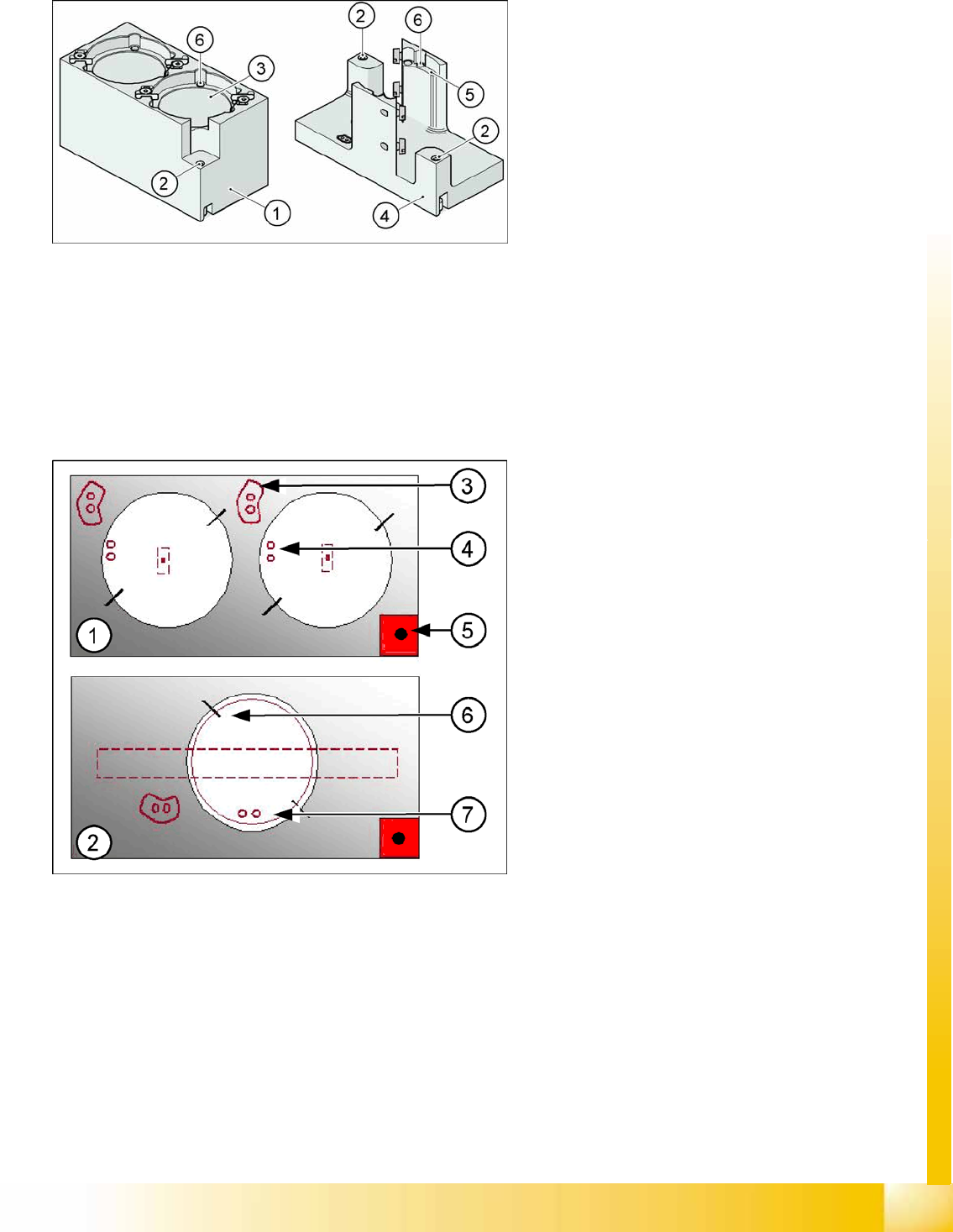
9.5.1.4 Function Description
The magazine for standard nozzles has 1 positioning fiducial for position detection, while the magazine
for special nozzles/grippers has two positioning fiducials. The nozzles are fixed by balls in the holder.
They are then either locked for return or released for pickup, depending on the direction of rotation of the
D axis.
Position of the nozzle in the magazines
9-20: Magazine for standard and special nozzles (HF/X/D3 machine shown
here as example)
Legend
1. Standard magazine
2. Positioning fiducia
3. Nozzle garage
4. Magazine for special nozzles
5. Nozzle garage
6. Balls for lifting the nozzles
Legend
1. Double magazine for standard nozzles (pickup
angle SW 505 = 184°)
2. Magazine for special nozzles or grippers
(pickup angle SW 505 = 275°)
3. Index pins for correct positioning of nozzles in
magazine
4. Position of nozzle with the holes for the index
pins.
5. Calibration fiducial for determining the
magazine position
6. Nozzle centering pins
7. The magazines for the special nozzles are
turned by 90° degrees.