00196044-05 - sg x und x4i fse_en.pdf - 第379页
Twin Head Twin Head Axis Dynamics Axis Control S tudent Guide (FSE) SIPL ACE X Series and X4I Edition 01/2009 EN T win Head 379 9.6.1.1 Z axis 9-22: Flowchart illustrating the functio n of the Z axis at the Twin head
Twin Head
Axis Control Nozzle Changer for Twin head
Student Guide (FSE) SIPLACE X Series and X4I
Twin Head Edition 01/2009 EN
378
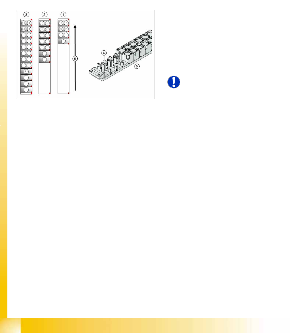
9.5.2 Nozzle Changer for Twin head
Die SIPLACE HF/HF3 and SIPLACE X machines configured with a Twin head are delivered with a
nozzle changer. This nozzle changer can accommodate up to 12 nozzle magazines. There are two
different magazine types available: standard magazines and magazines for special nozzles or grippers.
The nozzle changer may be installed depend on the configuration at location 1 and/or 3. The nozzle
changer consists of a standard module with 3 nozzle garages, for two nozzles each (standard nozzles)
and one nozzle garage for a special nozzle. This configuration can be extended as shown in the diagram
below.
9.6 Axis Control
9.6.1 Twin Head Axis Dynamics
Due to the wide component spectrum, no generally applicable oscillograms can be displayed for
correct axis function.
The axis dynamics can no longer be influenced by potentiometer settings.
The following function descriptions should help you analyze any malfunctions which occur.
The tables contain a brief description of the correct function and a description of malfunctions, their
possible causes and corresponding solution suggestions.
9-21: Nozzle changer configuration Twin- head
Legend
1. Standard nozzle changer
2. Extended Nozzle changer
3. Complete Nozzle changer
4. Magazine for 1 special nozzle
5. Magazine for 2 standard nozzles
6. Transport direction
NOTE:
The magazines for standard and
special nozzles are freely configurable
with SW 505 or higher.
Twin Head
Twin Head Axis Dynamics Axis Control
Student Guide (FSE) SIPLACE X Series and X4I
Edition 01/2009 EN Twin Head
379
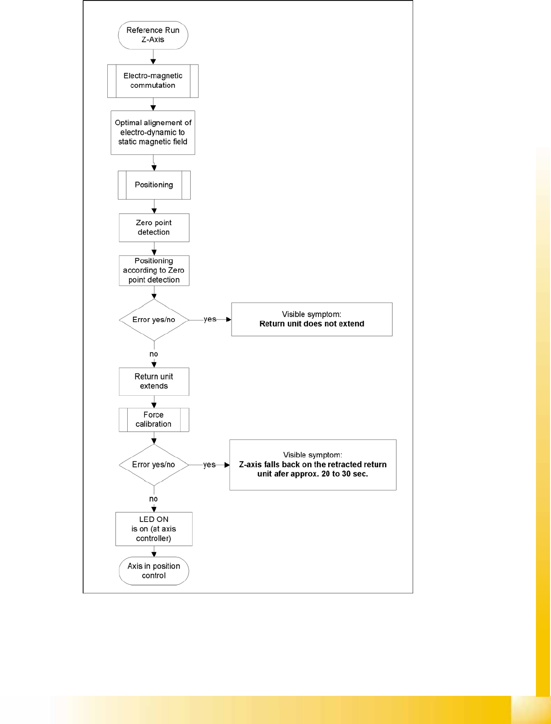
9.6.1.1 Z axis
9-22: Flowchart illustrating the function of the Z axis at the Twin head
Twin Head
Axis Control Twin Head Axis Dynamics
Student Guide (FSE) SIPLACE X Series and X4I
Twin Head Edition 01/2009 EN
380
During the Reference Run
Initial statements about the correct head function can be made from the individual procedures during the
reference run.
Z axis linear motor defect – replace the placement head.
Force measurement board defect – replace the placement head, due to the mechanical and electrical
calibration procedures required with special equipment.
During Nozzle Changeover
Function errors during nozzle changeover are not based on head axis function errors.
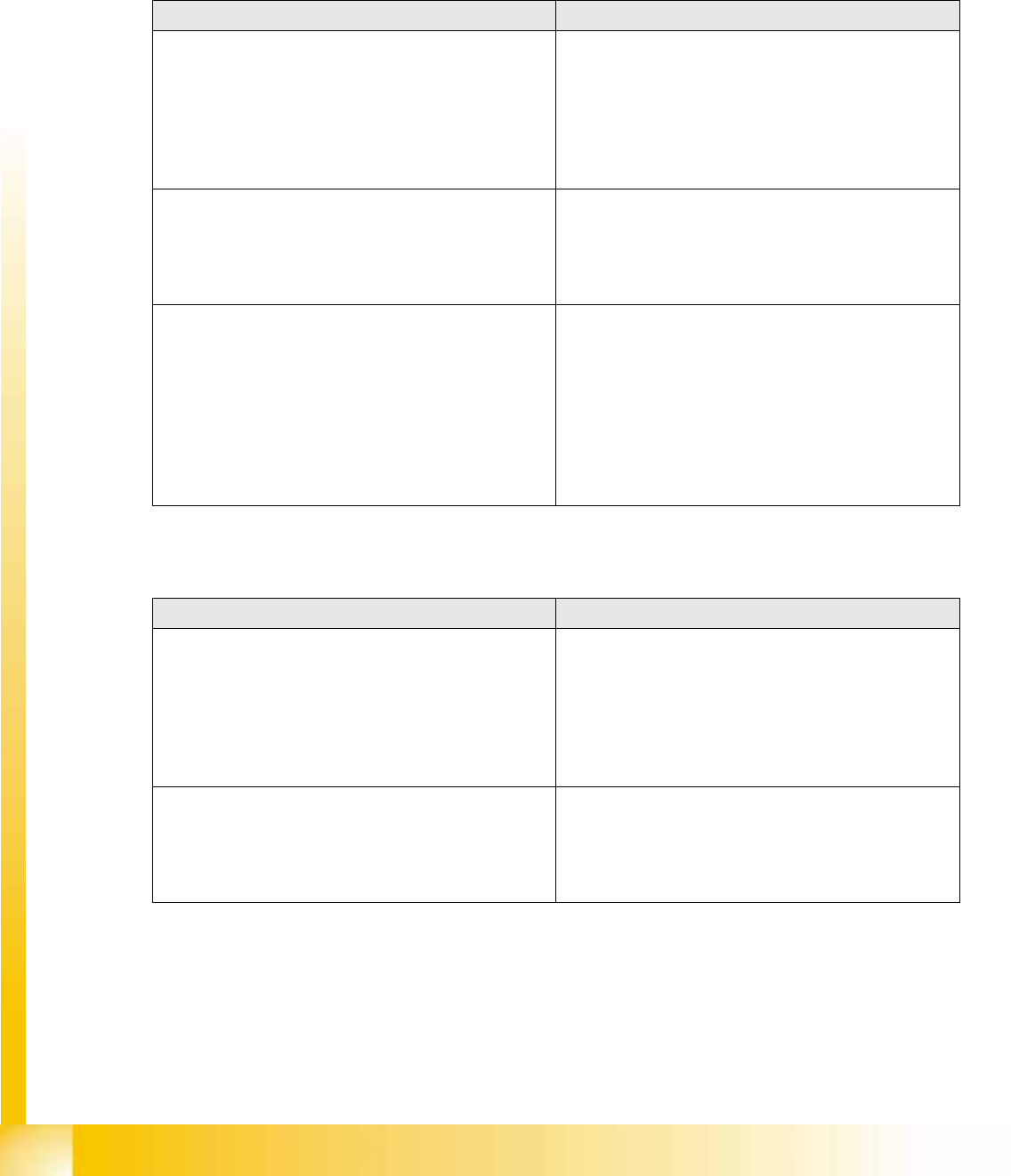
Detailed function: > Description > Result Malfunction: > Description > Cause/Solution
Axis reference run:
1. Search for phase current commutation
2. Zero point search
3. Position to calculated NPC target position
Result:
Servo-controlled Z axis is referenced.
Next step: force measurement board comparison.
Z axis unable to reach target position.
FM axis not correctly initialized.
Return cylinder does not move out.
Solution:
Remove mechanical stiffness (due to transport locks) or
replace head.
Force calibration:
Automatic calibration of force measurement board
during initialization.
Result:
Return cylinder moves out (downwards).
Force measurement calibration fails.
Return cylinder does not move out. Z axis falls down to
position of return cylinder, after 20-30 seconds.
Cause: Force measurement board defect.
Solution: Replace head
Height reference run
Test nozzle length at conveyor side:
Z axis tests nozzle length with 1 N placement force and
slow approach to conveyor side.
Travel speed is proportional to the value entered for the
spring pretension.
Twin head is moved to waiting position.
Threshold value: max. spring pretension should not
exceed 700 mN.
Height measurement fails.
Positioning ends with timeout error.
Z axis does not touch conveyor edge.
Cause: Incorrect entry for spring pretension with more
than 700 mN.
If this value is correct (according to the label), replace
the head.
Detailed function: > Description > Result Malfunction: > Description > Cause/Repair
Nozzle pickup:
Z axis travels in current sensor mode into the nozzle
interface, to engage.
The placement force is then reduced to facilitate rotation
of the D axis.
Result:
Z axis tests nozzle length after first pickup.
Z axis unable to reach target position.
Cause:
Nozzle rotated by 3° and inserted into garage at wrong
angle. X/Y position of nozzle changer (NC) not correctly
calibrated.
Solution:
Calibrate the nozzle changer.
Put down the nozzle:
Z axis travels with set force into the garage.
Rotate the nozzle to lock.
Z axis travels with set force up again.
Z axis unable to reach target position.
Cause:
Garage already occupied.
Nozzle has been manually attached at incorrect angle.
X/Y position of NC not correctly calibrated.