00196044-05 - sg x und x4i fse_en.pdf - 第385页
Twin Head Overview of Axis C ontrol for Z and D Axes Axis Control S tudent Guide (FSE) SIPL ACE X Series and X4I Edition 01/2009 EN T win Head 385 9.6.2.1 Overview of Positioning Times for T win Head Axis Mode/range Posi…
Twin Head
Axis Control Overview of Axis Control for Z and D Axes
Student Guide (FSE) SIPLACE X Series and X4I
Twin Head Edition 01/2009 EN
384
9.6.2 Overview of Axis Control for Z and D Axes
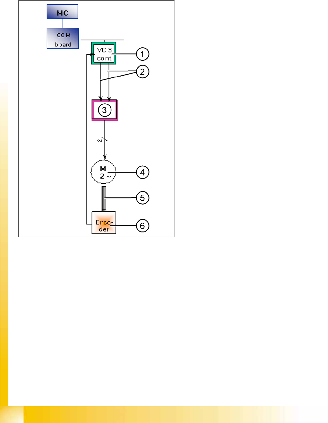
9-28: Axis control (shows D-axis as example)
The axis control system of the closed control loop
for the TWIN Head consists of the following main
components.
Axis controller A363 with VC3 controller or
A364
Servo amplifier (SDS)
Motor
Position measurement system incremental
scale and encoder
Legend
1. Axis controller board A363 with VC3 controller
(VC = Velocity Commutation/speed
commutation controller)
2. Control signals I nom "W" and I nom "U"
3. Servo amplifier function: Motor current limiter
dimensioned by semiconductor or motor load -
amplification of axis controller signals.
Determination of 3rd motor current signal.
Generation of 3 (2) AC motor signals from DC
supply.
The Z/D servo output signals are directly
connected to the motors. This guarantees
operator safety when the safety covers are
opened.
4. The Z axis has 3-phase AC motor with
integrated temperature sensor.
The D-axis has a 2-phase motor.
5. The motor and the incremental encoder are
fixed (rigid) to one another.
6. Incremental encoder: Traces the exact
position of the axis via the track signal.

Twin Head
Overview of Axis Control for Z and D Axes Axis Control
Student Guide (FSE) SIPLACE X Series and X4I
Edition 01/2009 EN Twin Head
385
9.6.2.1 Overview of Positioning Times for Twin Head
Axis Mode/range Positioning time
Z Absolute positioning, free space/travel range 90000 digits = 45000 µm
(resolution 0.5 µm)
75 ms +/-3 ms
Z Absolute positioning, free space/travel range 54200 digits = 27100 µm
(resolution 0.5 µm)
57 ms +/-3 ms
Z Current sensor (for force measurement) on conveyor edge 516 nozzle
travel profile 5, force 2 N
approx. 78 ms*
*see below for details
Z Current sensor (for force measurement) on conveyor edge 516 nozzle
travel profile 7, force 5 N
approx. 78 ms*
*see below for details
Z Current sensor (for force measurement) on conveyor edge 516 nozzle
travel profile 7, force 10 N
approx. 65 ms*
*see below for details
Z Current sensor (for force measurement) on conveyor edge 516 nozzle
travel profile 25, force 15 N
approx. 70 ms*
*see below for details
d 10000 digits = 10 degrees 90 ms +/-10 ms*
*see below for details
d 90000 digits = 90 degrees 150 ms +/-20 ms*
*see below for details
d 180000 digits = 180 degrees 190 ms +/-20 ms*
*see below for details
NOTE:
Z axis
The Z axis positioning time in the current or force sensor mode does not permit direct
conclusions about the functions. In order to check the function of these modes, please use an
oscilloscope or perform force measurement during placement.
NOTE: D Axis
The positioning times between the left and right turns of the sleeve may deviate from one
another considerably. However, the time characteristic of this axis is not critical for Twin head
operation, due to the placement procedure.
Twin Head
Axis Control Twin Head Axis Track Signals
Student Guide (FSE) SIPLACE X Series and X4I
Twin Head Edition 01/2009 EN
386
9.6.3 Twin Head Axis Track Signals
The track signals play a greater role with the new drive concept for HF machines. They are responsible
for the exactly and precise positioning of the axes and are used as the only feedback signal in the closed-
loop control system, meaning that they have an important influence on the axis dynamics.
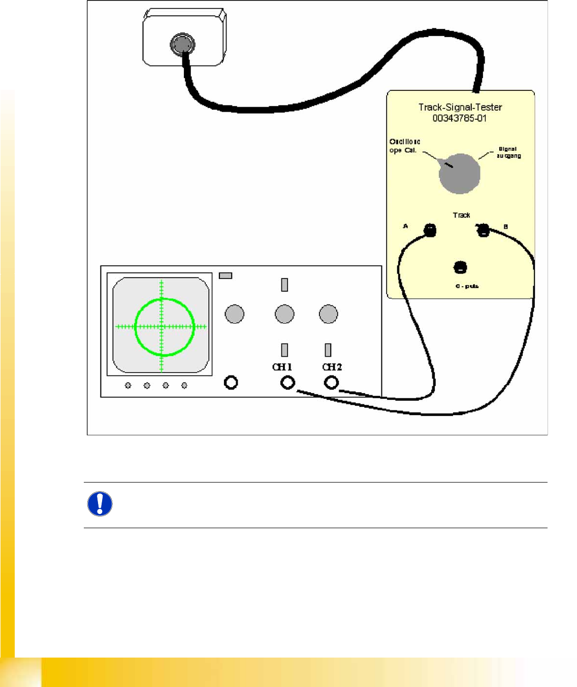
9.6.3.1 Measurement Setup
9-29: Measurement setup for the analog track signals of the Twin head Z axis
The analog track signals of the Twin head Z axes are counted by the incremental encoder.
NOTE:
The digital track signals for the Twin head can only be measured at the axis test box. The track
signals for the Twin head D-axis can only be measured as digital signals at the axis test box.